Stroke-controlled aspiration and dispensing
Use step counts to organize aspiration, dispensing and refill for reagent addition, dilution and buffer dispensing in analytical instruments.

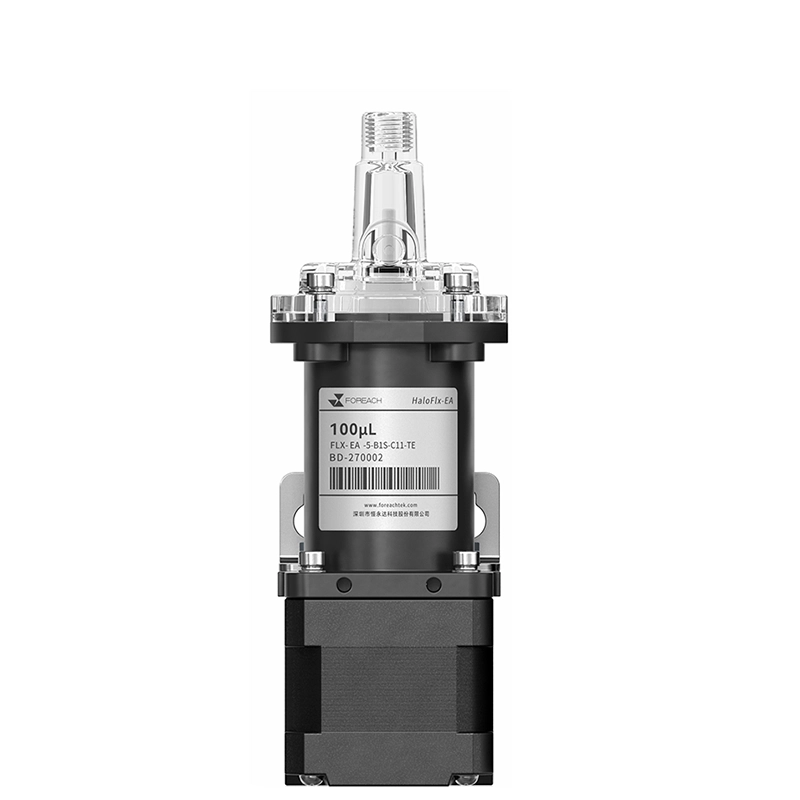
EA-100-PMMA is a precision dispense pump with a nominal capacity of 100 μL for microliter reagent addition, small-volume sample handling and reaction-liquid addition in analytical instruments. An acrylic (PMMA) head and ceramic piston work with a reciprocating stepper drive to aspirate and dispense measured volumes.
Ports are available in 1/4-28 UNF or M6, with 2000 steps per full stroke. Full-stroke accuracy and repeatability are both ≤0.5%, with an anticipated life of 5 million cycles. Optical feedback, valve assemblies and a controller can be supplied to integrate the microliter dispensing unit with instrument controls.
OEM customization includes PMMA, PCTG and PEEK head options, with zirconia ceramic, alumina ceramic, PEEK or sapphire pistons. Motor, port and fluidic component choices can be matched to reagent chemistry, available space and the dispensing sequence.
Application Areas:
IVD, Life Sciences, Laboratory Automation, Analytical Instruments
Select capacity, pump head material and accessories, then save different configurations for your inquiry.
| Nominal capacity | 100 μL |
|---|---|
| Pump head material | PMMA (polymethyl methacrylate); Transparent |
| Piston / seal | Ceramic / UHMWPE (ultra-high-molecular-weight polyethylene) |
| Fluid port | 2 × 1/4-28 UNF flat-bottom ports; M6 optional |
| Basic motor configuration | 1.8°; 2000 steps per full stroke |
| Nominal resolution | 0.05 μL/step (100 μL ÷ 2000 steps) |
| Other stroke configurations | 0.9°; 4000 steps per full stroke; 0.025 μL/step |
| Lead screw pitch | 1.27 mm |
| Mounting | 2 × M3; standard spacing 31.8 mm, wide bracket 42.8 mm |
| Accuracy / repeatability at 100% stroke | ≤0.5% / ≤0.5% |
| Accuracy / repeatability at 2% stroke | ≤2.0% / ≤1.5% (piston-travel test) |
| Backlash | ≤1.0%; validate compensation for precise dosing |
| Fluid pressure | <0.30 MPa |
| Expected service life | 5 million cycles (pure water, room temperature, 50 kPa back pressure) |
| Fluid / ambient operating temperature | 15–40 ℃ / 5–40 ℃ |
| Operating humidity | 30%–85% RH, non-condensing |
Nominal resolution is capacity divided by full-stroke steps, not the minimum reliable dose. 2% of 100 μL is 2 μL. Validate actual reagent results at this dose with the selected valves, tubing, back pressure and drive settings.
Low-range figures are tested by piston travel. Match the motor, optical sensor, valve and driver to the selected configuration; capacity or head material alone does not define all electrical options.
EA uses a stepper motor to reciprocate the piston for aspiration and dispensing. Define dose volume, consecutive dispenses, fluid and cycle time before choosing capacity, wetted materials, valves and controls.
Use step counts to organize aspiration, dispensing and refill for reagent addition, dilution and buffer dispensing in analytical instruments.
Define dose volume and doses per cycle before comparing 100, 250 and 500 μL configurations. For small doses, also check refill timing and repeatability at the target operating point; do not select solely by maximum capacity.
The transparent head allows observation of filling and bubbles. PMMA (polymethyl methacrylate) is not resistant to alcohol or strong acids; both process and cleaning fluids must meet these material limits.
Select the stepper motor, home sensor or encoder to suit the instrument. A home sensor detects the initial position; it does not provide closed-loop motion control.
Select valve assemblies and drivers for the fluid path and controls. Include aspiration, dispensing and valve switching in the complete cycle.
Expected life: 5 million cycles with pure water at room temperature and 50 kPa backpressure. Saline or crystallizing fluids require flushing and shutdown procedures.
The nominal capacity is 100 μL. Define dose volume and doses per cycle before comparing 100, 250 and 500 μL configurations. For small doses, also check refill timing and repeatability at the target operating point; do not select solely by maximum capacity.
| Step angle | Full steps per stroke | Nominal volume per step |
|---|---|---|
| 2000 steps | 0.05 μL/step | |
| 4000 steps | 0.025 μL/step |
200steps
10 μL ÷ 100 μL × 2000 steps = 200 steps
Nominal steps are for command conversion, not the minimum reliable dose or measured accuracy.Calculated from capacity and full-stroke steps; volume per step is rounded for display. Validate microstepping, backlash, bubbles, valves and tubing at the target volume.
Take up mechanical backlash after reversal before counting the effective dosing stroke. The ≤1.0% backlash figure is a pump specification; set compensation and valve timing for the actual circuit.
2000 × 1% = 20 steps
Conversion example only; validate the actual compensation.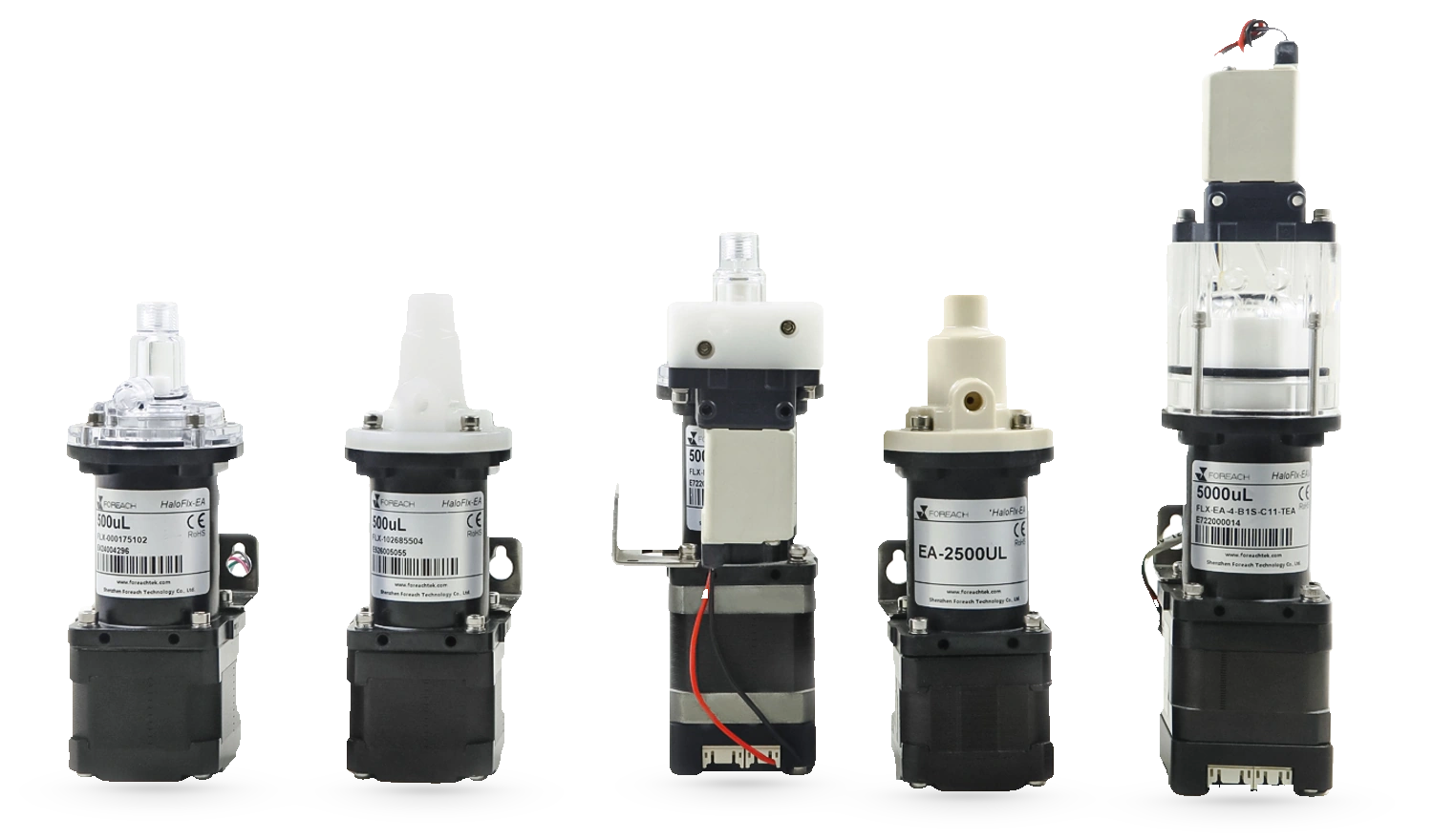
Record composition, concentration, temperature and contact time for both working and cleaning fluids, then consider visibility or light shielding. This model uses a PMMA (polymethyl methacrylate) head. The table compares EA materials; changing the comparison does not change the model or supplied configuration.
Scroll horizontally to see all material limits and selection criteria.
| Head material | Main selection considerations | Limits and selection criteria |
|---|---|---|
| PMMA (Polymethyl methacrylate)Transparent · Current head | For fluid paths requiring direct observation of filling and bubbles. | Not resistant to alcohol or strong acids. Select another material if either the process or cleaning fluid contains them. |
| PCTG (Copolyester)Transparent | Compare with PMMA (polymethyl methacrylate) and PSU when a transparent head is needed. | Not resistant to strong acids, strong alkalis, sodium hypochlorite or “84” disinfectant. Transparency alone is not a reason to substitute it for PMMA (polymethyl methacrylate). |
| PSU (Polysulfone)Transparent | Consider specific grades when transparency, hydrolysis resistance and thermal stability matter. | General resin properties do not mean the pump can operate at high temperature or be steam-sterilized. Select according to the pump, seals and actual cleaning conditions. |
| PEEK (Polyether ether ketone)Opaque | Include in chemical compatibility comparisons when an opaque head is needed or the current material does not meet fluid requirements. | Check the specific chemical, concentration and temperature. PEEK is not universally resistant to all acids, alkalis and solvents. |
| PVDF (Polyvinylidene fluoride)Opaque | Consider when an opaque head is required and acids, salts or other chemical fluids are involved. | Check every process and cleaning fluid, especially alkaline and mixed formulations. Resin compatibility charts do not replace complete-pump testing. |
| PPS (Polyphenylene sulfide)Opaque | An opaque EA option; compare construction and material compatibility. | Confirm the actual grade, fluid and seal design before choosing a combination. Opacity does not establish chemical compatibility. |
| POM (Polyoxymethylene)Opaque | An opaque EA option; compare machining, construction and fluid requirements. | Check acids, oxidizing cleaners and prolonged immersion separately. Do not substitute based on the suitability of other plastics. |
| PET (Polyethylene terephthalate)Opaque | An opaque EA project option. | Confirm the actual resin grade and compatibility with the target fluid before proceeding to a prototype. |
PMMA (polymethyl methacrylate) restrictions also apply during cleaning. PCTG is limited with strong acids, strong alkalis and sodium hypochlorite. Reassess the full formulation when changing material; opacity alone does not imply corrosion resistance.
EA piston options include zirconia, alumina and PEEK. This page describes a ceramic piston. A PEEK piston requires separate wetted-path evaluation. Ceramic grade, surface and seal pairing depend on the supplied configuration.
Seals use UHMWPE (ultra-high-molecular-weight polyethylene). After changing the head material, check seals, piston, valves, tubing and fittings. For saline or crystallizing fluids, consider crystal damage and seal-flushing options.
General PSU, PEEK and PVDF properties are screening references, not confirmation of FOREACH resin suppliers or changes to pump temperature, pressure or validation requirements. References: PSU properties, PEEK chemical compatibility, PVDF chemical compatibility.
View material compatibility referencesIdentify the motor by label, part number and wiring documents before selecting a driver. Step angle determines nominal steps; four- or six-wire construction determines winding connections. Do not infer all electrical parameters from the harness.
| Rated phase current | 1.2 A/phase |
|---|---|
| Winding resistance (25 °C) | 2.8 Ω ±10% |
| Winding inductance (1 kHz) | 4.5 mH ±20% |
Four motor leads do not mean a four-position connector. The drawing shows assigned pins in a six-position connector; identify windings and pins from the drawing.
Match phase current, microstepping and acceleration/deceleration to the driver definitions. Rated phase current is not supply input current. Check current settings, then verify motion and temperature rise.
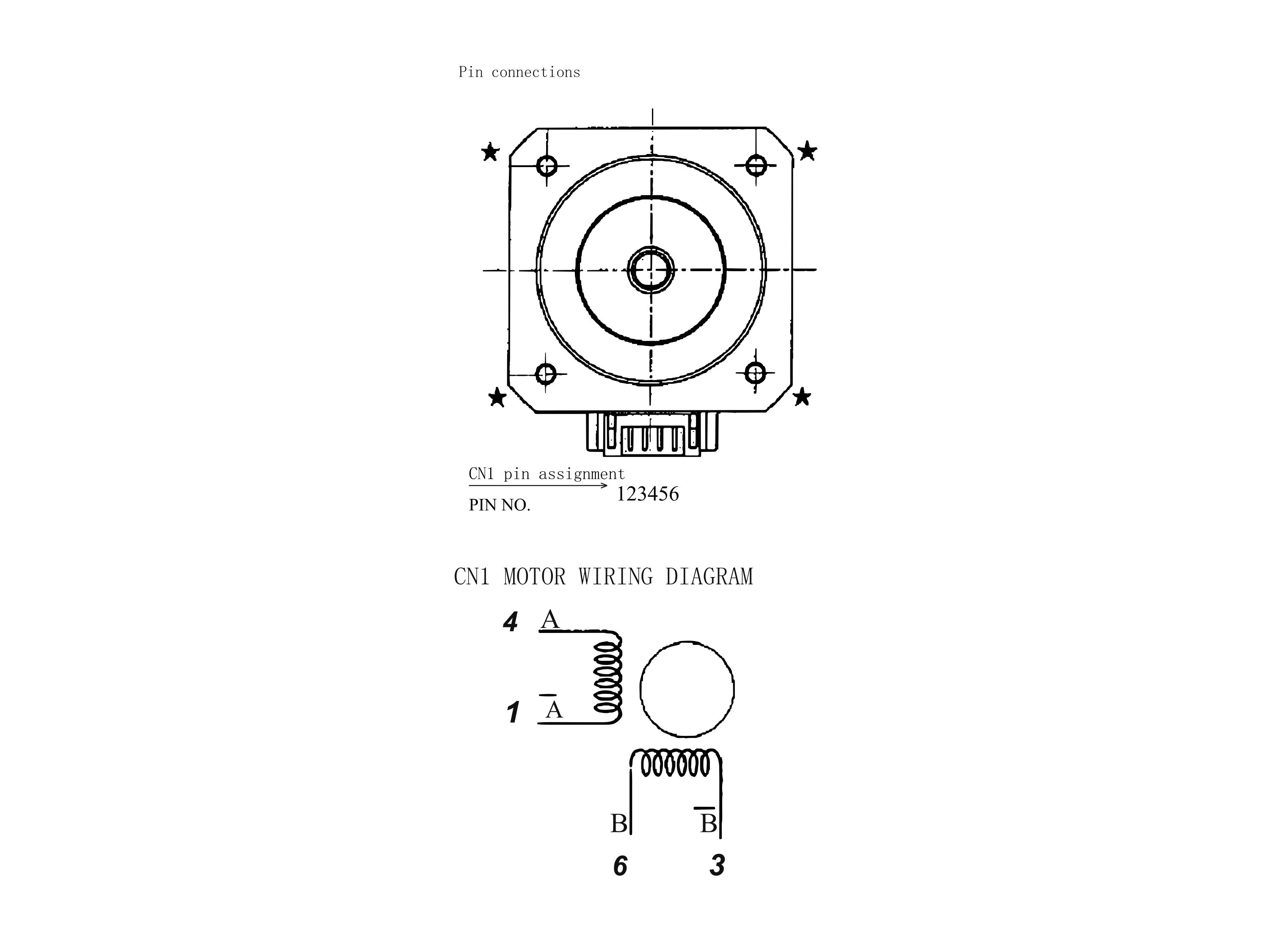
A stepper motor needs a matching driver. RS-232, RS-485 and CAN belong to the optional ISC1000 integrated driver, not the bare pump. Confirm valve, driver and closed-loop encoder options separately.
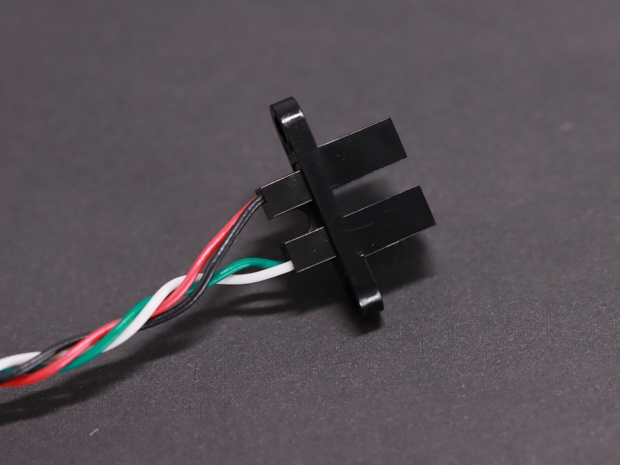
The optical sensor detects the initial position for homing; an encoder provides a different type of motion feedback. They are not interchangeable. EA also offers no-sensor or custom-sensor options; three common configurations are compared below.
Powered sensor with signal output; first verify board input levels and output mode.
| Wire | Connection and function |
|---|---|
| Brown | 5–24 V DC supply |
| Blue | Supply return |
| Black or white | Signal output; use the output for the supplied version and verify light-on/dark-on behavior |
The diagram shows two output modes. Not all shown wire colors belong to one three-wire harness.
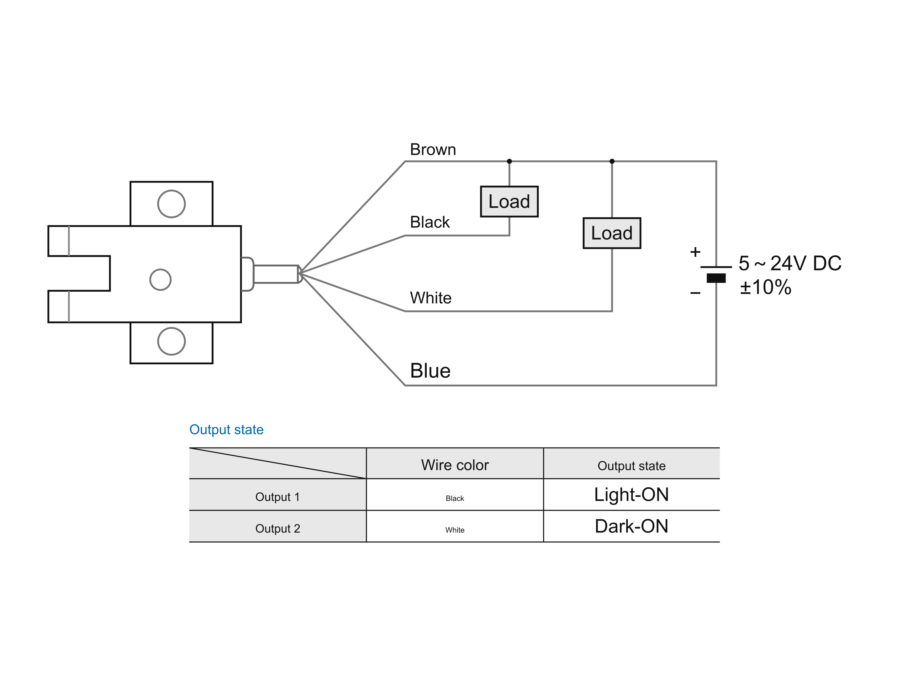
Read blocked and unblocked states first. Confirm the input active level, homing direction and stop logic before automatic homing. Validate stopping clearance for the mechanism; do not copy step counts from other capacities or versions.
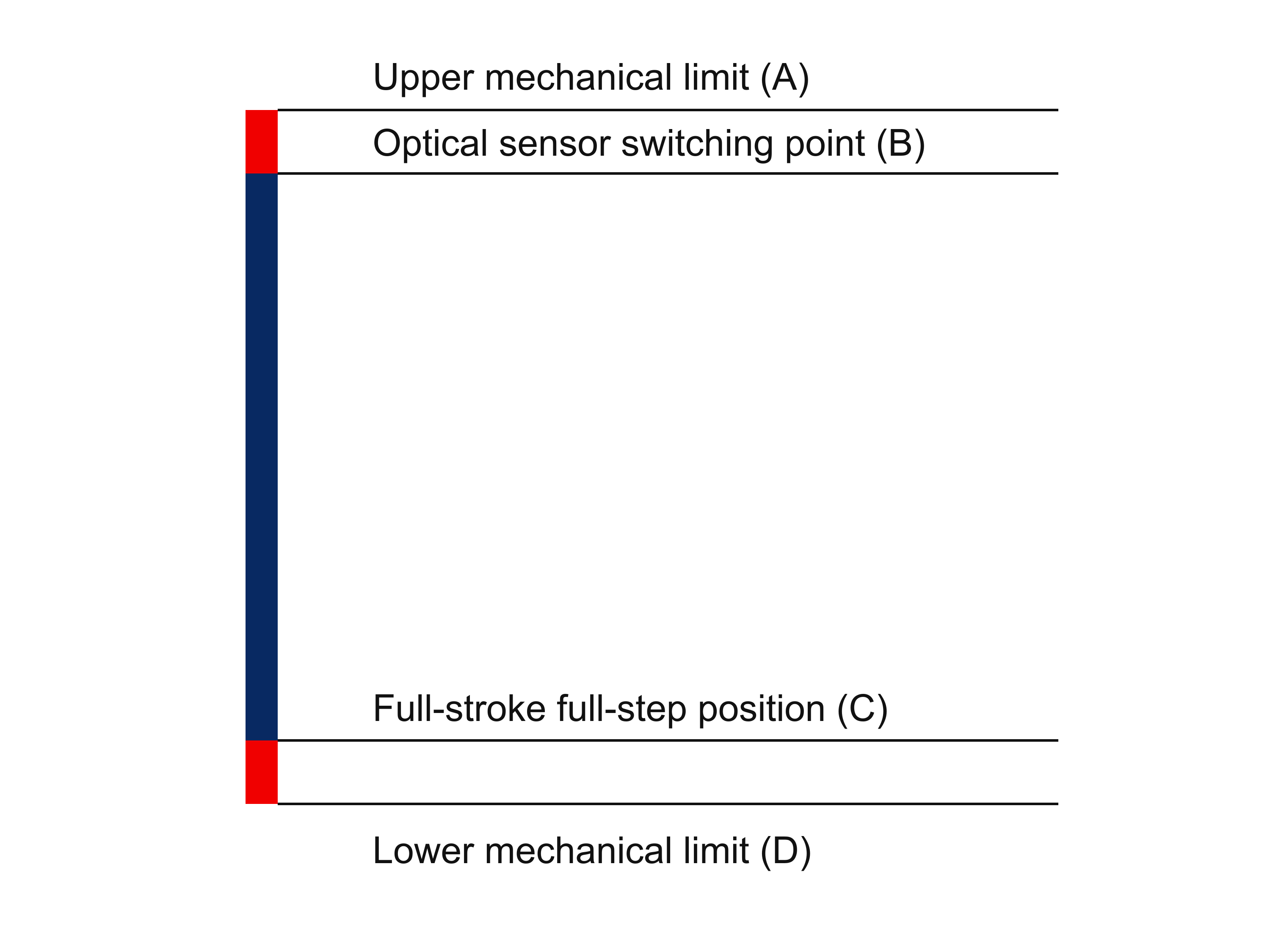
With a home sensor, initialization after each test cycle is recommended. Match stopping clearance to the mechanism, homing speed and stop logic to avoid mechanical contact.
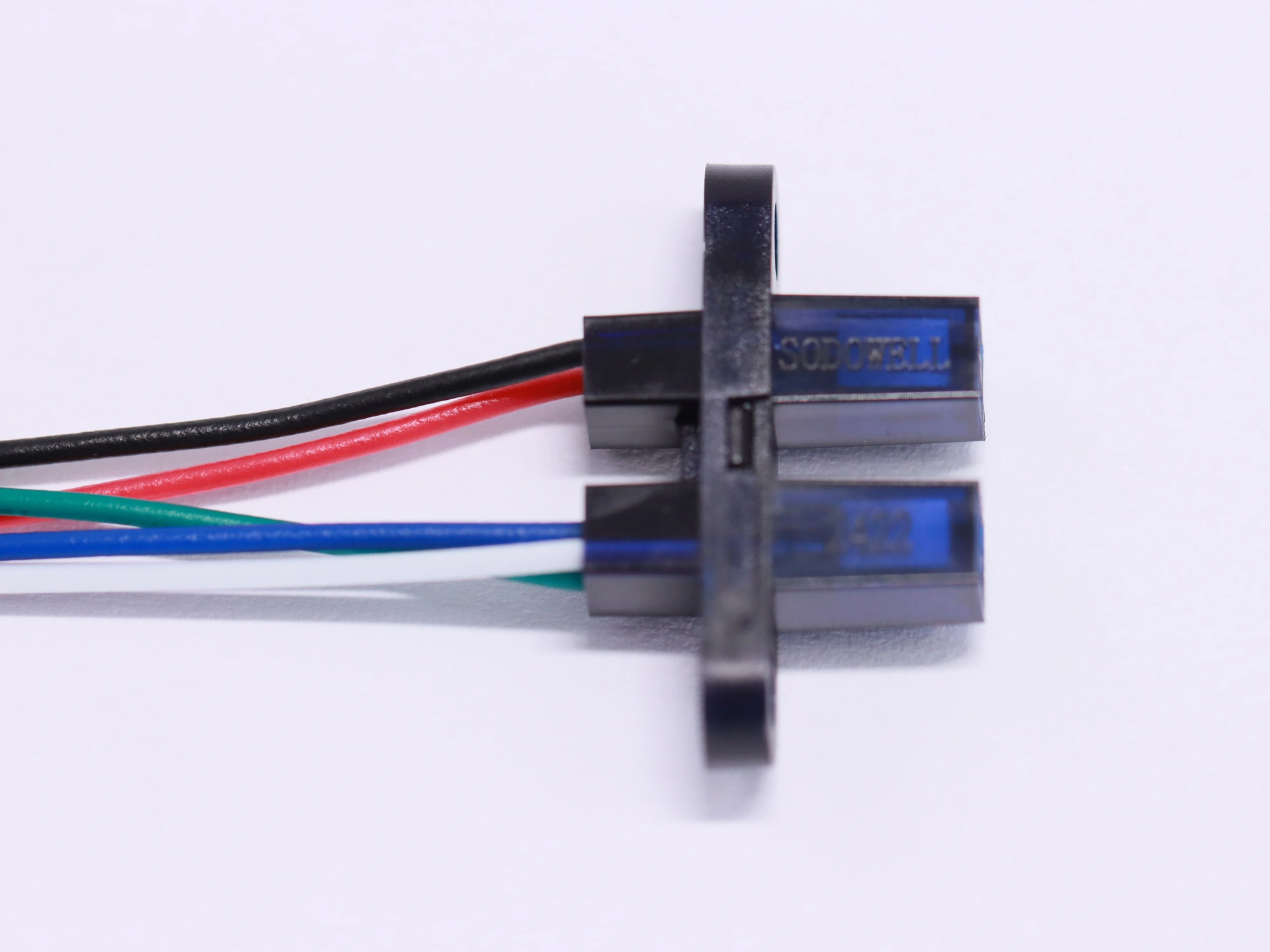
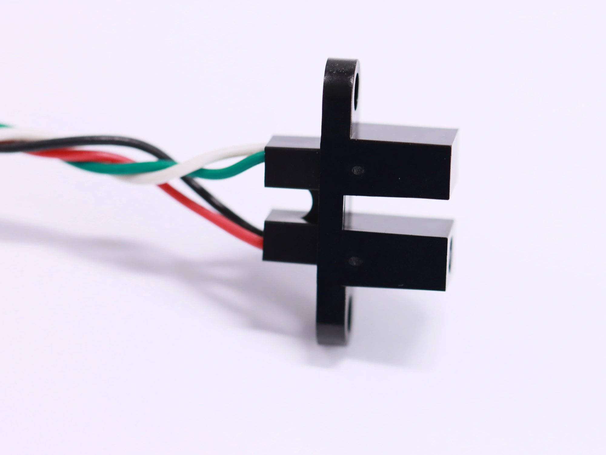
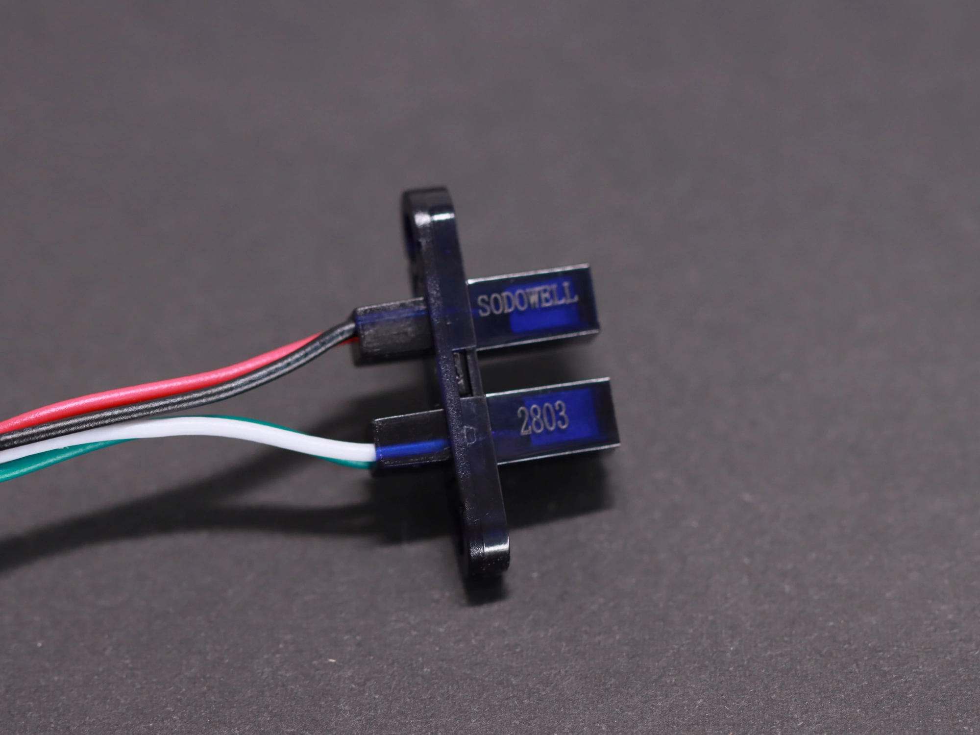
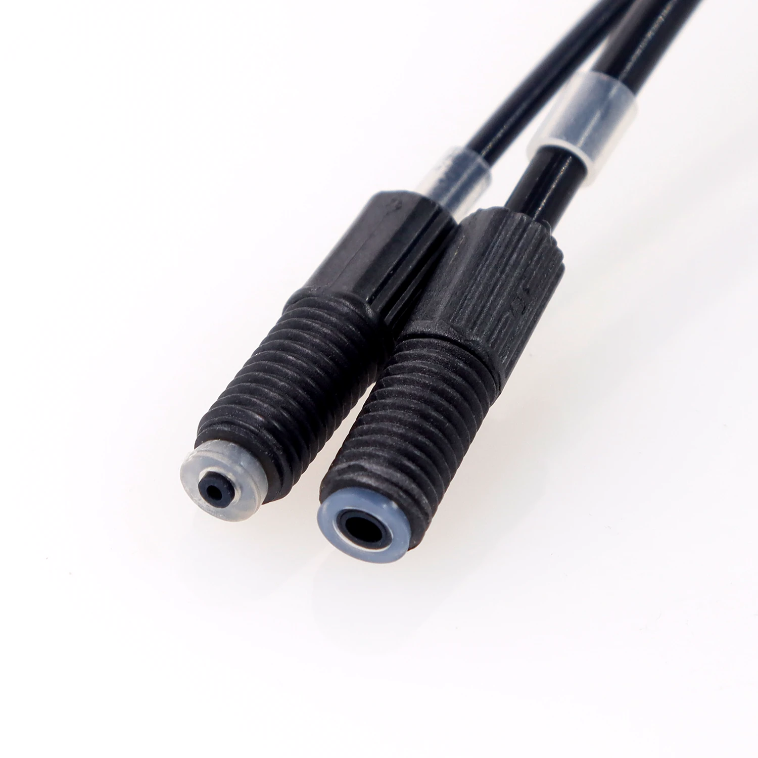
Standard ports are 2 × 1/4-28 UNF flat-bottom; M6 is optional. Check thread, depth, tube OD, fitting and washer together. Identical threads do not guarantee identical sealing geometry.
Compare rigid PTFE, FEP, PFA and PEEK tubing for precision dosing, with matching flanged/washer or ferrule connections. For doses up to 20 μL, rigid tubing downstream of the shut-off valve is recommended.
Check bare-pump, pump/valve and driven configurations separately. Confirm EAV, EAD or EAVD when integration is needed; optional parts are not automatically included.
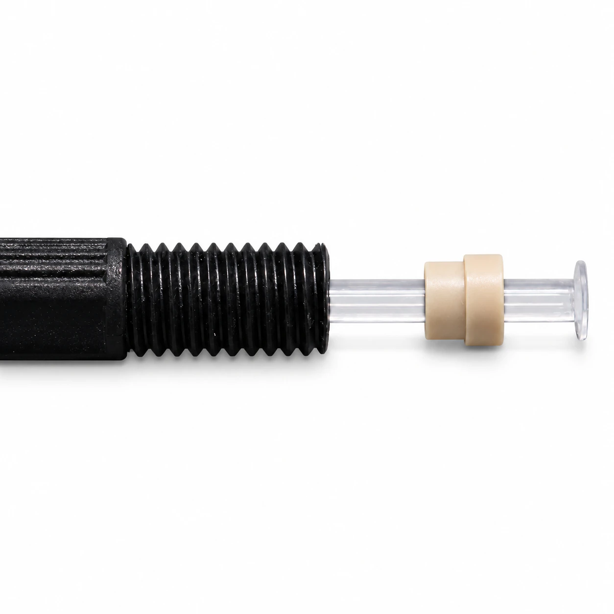
Threaded fittingSupport washerFlanged tube end
The tube end is pre-flanged. The fitting presses the flange through a matching support washer against the sealing face of the flat-bottom port.
Dedicated tooling is needed to form the flange. Check flange integrity and the fit of washer and port during assembly.
Threaded fittingMatching ferruleUnflanged rigid tube
No pre-flanging is needed. Use matched fittings and ferrules for on-site assembly of rigid tubing. Tube outside diameter, ferrule and port must match as a set.
The ferrule occupies axial space; check hole depth separately. It is generally not intended for reuse after repeated disassembly.
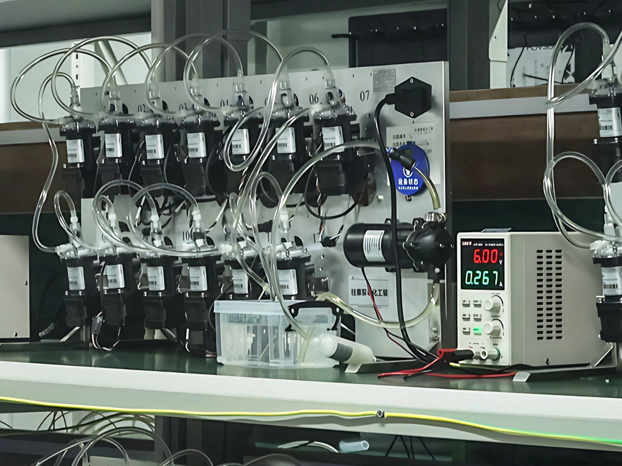
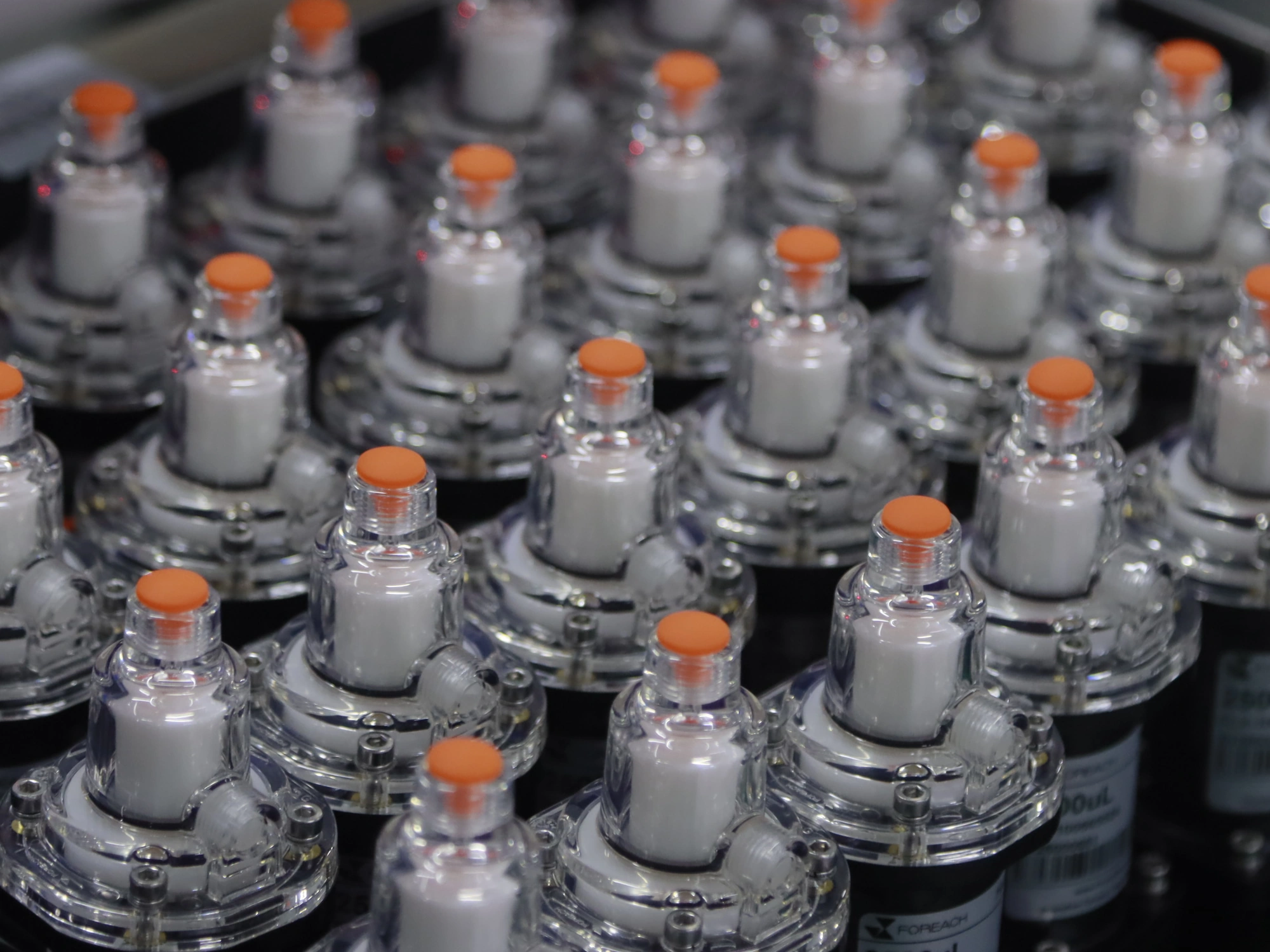
Check capacity, head, ports, motor, sensor and valves against harness labels and drawings. Stop the instrument and disconnect power before mounting, wiring or changing tubing.
Brackets use 2 × M3 holes with 31.8 mm standard spacing or 42.8 mm wide spacing. Check this model’s mounting drawing, preferably orient the outlet upward, and leave space for fittings and wiring. Do not transmit tubing tension to the head.
Check 1/4-28 UNF or M6 ports, hole depth, fittings and seals. Recommended torque for the corresponding plastic fittings is 0.25–0.30 N·m. If only one port is used, seal the other with a suitable plug. Do not replace flat-bottom seals with PTFE tape or thread sealant.
Use the motor diagram above to check windings and terminals, then the selected sensor diagram for supply and signal. Verify signal levels, pull-up/current-limiting circuits and the blocked-state polarity before powering on.
Set phase current, microstepping and acceleration/deceleration for the supplied motor and driver. With a sensor, verify blocked state, direction and stopping clearance after triggering. Reinitializing homing after each test cycle is recommended according to the control sequence.
Prime with fluid compatible with all wetted materials. Repeat aspiration and dispensing to flush the chamber, valves and tubing, checking bubbles and leaks. Coordinate motion with the actual valve circuit; do not run dry for prolonged periods.
Set and verify backlash compensation in the program, then repeat aspiration/dispensing at the target volume and record collected amounts. For doses up to 20 μL, rigid tubing downstream of the shut-off valve is recommended. Also check bubbles, tubing elasticity and valve timing.
After priming, homing and backlash compensation, repeatedly collect the same target volume and record results with a consistent measurement method.
Record nominal steps, piston-stroke specifications and actual reagent delivery separately. Accept volume and repeatability at the target operating conditions.
| Symptom | Check first |
|---|---|
| Delayed delivery or an undersized first dose | Check chamber/tubing bubbles, fitting seals and valve timing. Re-prime and remove air, then compare collected volumes. |
| Small-dose variation or error after reversal | Check backlash compensation, tubing downstream of the valve and steps for the target dose. Repeat measurements under identical conditions. |
| Motor vibration or intermittent motion | Check supplied motor, drive current, microstepping and acceleration/deceleration, along with tubing resistance and mechanical load. |
| Port leakage or head cracks | Stop operation and check fluid compatibility, flat-bottom seals and fitting torque. Retain the label, site photos and operating records, and contact service. |
Install and wire according to the supplied version. Contact technical support for modifications, disassembly, repairs or jamming.
Nominal capacity is 100 μL with 2000 basic full-stroke steps, or 0.05 μL/step. This ratio converts motion commands. Validate the minimum reliable dose at the target volume, accounting for bubbles, backlash, valve operation and tubing elasticity.
Share the target volume, fluid compatibility, port type, control method, installation space, and service-life requirements. The Foreach engineering team can help confirm the pump configuration and wetted materials.