
Confirm performance for the reagent-sensitive wavelengths and actual shielding requirements. Black appearance alone does not replace light-shielding validation of the complete fluid path.
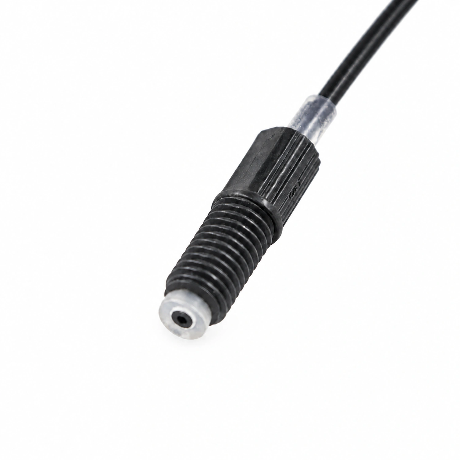
Black PTFE Ferrule Tubing Assembly
FOREACH black PTFE ferrule tubing assemblies connect black PTFE tubing with matched threaded fittings and ferrules for reagent lines requiring light shielding in in-vitro diagnostic (IVD) and automated analytical instruments. No tube pre-flanging is required. Reference tubing IDs span 0.8–2.0 mm, with ODs of 1.6, 2.0, 2.5, 3.0 and 3.2 mm in specified pairs. Length, both end connections and line identification can be specified.
Standard connections fit M6×1 or 1/4-28 UNF flat-bottom ports, with fitting material, structure and ferrule selected for tube dimensions and port model. Evaluate shielding against reagent-sensitive wavelengths, tube-end connections and the actual installation. Protective sleeves and stop tubes are optional; text, numbers or logo labels can identify fluid paths. Samples to drawing, instrument integration and batch assembly are supported. Confirm working pressure and temperature for the specific dimensions, ports and complete assembly.
FOREACH holds ISO 9001 and ISO 13485 quality management system certifications.
Typical Applications:
Reagent lines requiring light shielding, Black PTFE ferrule connections, End connections without pre-flanging, Identified instrument fluid paths
| Tubing material and appearance | Black PTFE |
|---|---|
| Connection structure | Ferrule connection; no tube pre-flanging required |
| Fitting structure | Standard, compact |
| Fitting material | PPS, PVDF, PEEK, POM, PP; selected by series |
| Thread sizes | M6×1, 1/4-28 UNF |
| Ferrule material | PP, ETFE; matched to the model |
| Finished length | Custom to drawing, with specified length and tolerance |
| A/B ends | Fitting material, thread and connection type can be specified separately |
| Optional configurations | Coils, abrasion protection sleeves, stop tubes, heat-shrink labels |
Tube Size Combinations
| Tube OD (mm) | Matching Tube ID (mm) |
|---|---|
| 1.6 | 0.8 |
| 2.0 | 1.0 |
| 2.5 | 1.5 |
| 3.0 | 2.0 |
| 3.2 | 1.6 |
These are available tubing sizes. Confirm end dimensions and mating ports against the assembly drawing.
Match fitting material, structure and thread to the corresponding model.
Working pressure and temperature must be confirmed for the specific assembly configuration.
Matching fittings and 2D drawings
The table lists fitting series, threads and body materials for 1.6 mm tube OD as examples. Select the drawing by material and full model number; confirm matching parts for other ODs during customization.
| Fitting series | Thread size | Nut material | Fitting drawing |
|---|---|---|---|
| HN | M6×1 | PVDF, PPS, PEEK, POM | |
| HN | 1/4-28 UNF | PVDF, PPS, PEEK, POM | Confirm for the selected model |
| HNF | M6×1 | PVDF | |
| HNF | 1/4-28 UNF | PVDF | |
| HN6 | M6×1 | PVDF, PPS, PEEK, POM | |
| HN6 | 1/4-28 UNF | PVDF, PPS, PEEK, POM | |
| HNF6 | M6×1 | PPS | |
| HNF6 | 1/4-28 UNF | PPS |
Frequently Asked Questions
Submit your requirements
Prepare an assembly drawing, port drawing or BOM, together with sample quantity, batch requirements and acceptance criteria.