500 μL nominal capacity
Plan dispensing and refill cycles after each aspiration using dose volume, consecutive dose count and instrument cycle time. For small target doses, also compare smaller-capacity pumps at that operating point.

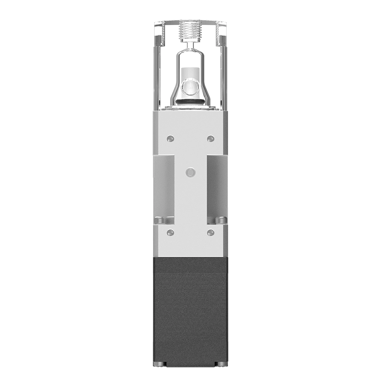
SM-500-PMMA is an OEM miniature dosing pump with a nominal capacity of 500 μL for reagent addition, metered diluent delivery and sample handling in small automated instruments. Its PMMA head and ceramic piston use a reciprocating stepper drive for metered aspiration and dispensing.
Ports are available in 1/4-28 UNF or M6, with 2000 steps per full stroke. Full-stroke repeatability is ≤0.5%, with an anticipated life of 5 million cycles; dispensing accuracy is confirmed for the selected configuration. Optical feedback, valve assemblies and a controller coordinate dispensing actions with the instrument program.
Head options are PMMA, PSU, POM and PEEK, with ceramic, stainless steel or PEEK pistons. Dispensing probes, tubing, controller and mounting arrangements can be matched to reagent and diluent properties to build a dosing unit suited to the instrument layout.
Application Areas:
Select capacity, pump head material and accessories, then save different configurations for your inquiry.
| Nominal capacity | 500 μL |
|---|---|
| Pump head material | PMMA (polymethyl methacrylate); Transparent |
| Piston / seal | Ceramic / UHMWPE (ultra-high-molecular-weight polyethylene) |
| Fluid port | 2 × 1/4-28 UNF flat-bottom ports; M6 optional |
| Basic motor configuration | 1.8°; 2000 steps per full stroke |
| Nominal resolution | 0.25 μL/step (500 μL ÷ 2000 steps) |
| Other stroke configurations | 2400-step configuration; 2400 steps per full stroke; 0.208333 μL/step / 4000-step configuration; 4000 steps per full stroke; 0.125 μL/step |
| Working stroke | 12.7 mm |
| Mounting | 4 × M3; spacing 15 × 35 mm |
| Accuracy / repeatability at 100% stroke | 0.5% / 0.5% |
| Repeatability at 2% stroke | 1.5% (with backlash compensation) |
| Backlash | <1.0%; validate compensation for precise dosing |
| Fluid pressure | <0.30 MPa |
| Expected service life | 5 million cycles (pure water, room temperature, 50 kPa back pressure) |
| Fluid / ambient operating temperature | 15–40 ℃ / 10–40 ℃ |
| Operating humidity | 30%–85% RH, non-condensing |
Nominal resolution is capacity divided by full-stroke steps, not the minimum reliable dose. 2% of 500 μL is 10 μL. Validate actual reagent results at this dose with the selected valves, tubing, back pressure and drive settings.
Low-range repeatability assumes backlash compensation. Match wiring, ports and mounting holes to the supplied version; do not transfer them between series.
SM-500-PMMA is designed for aspiration and metered dispensing inside instruments. The miniature design uses a 28-size stepper motor. Check capacity, working stroke, four-hole mounting and drive configuration together.
Plan dispensing and refill cycles after each aspiration using dose volume, consecutive dose count and instrument cycle time. For small target doses, also compare smaller-capacity pumps at that operating point.
The transparent head allows observation of filling and bubbles. PMMA (polymethyl methacrylate) is not resistant to alcohol or strong acids; both process and cleaning fluids must meet these material limits.
4 × M3; spacing 15 × 35 mm. Check working stroke and mounting dimensions separately. Leave room for fittings, wiring and moving parts.
2000, 2400 and 4000 steps represent different full-stroke configurations. Step angle alone does not identify the stroke; calculate volume per step for the selected version.
The SM bare pump requires a stepper driver. For an integrated valve and communication control, check SMVD. RS-232, RS-485 and CAN belong to the corresponding driver configuration and cannot connect directly to bare motor leads.
Fluid temperature 15–40 ℃, Fluid pressure <0.30 MPa. Expected service life 5 million cycles (pure water, room temperature, 50 kPa back pressure); validate with the actual fluid, drive and maintenance conditions.
Plan dispensing and refill cycles after each aspiration using dose volume, consecutive dose count and instrument cycle time. For small target doses, also compare smaller-capacity pumps at that operating point.
| Stroke configuration | Full steps per stroke | Nominal volume per step |
|---|---|---|
| 2000 steps | 0.25 μL/step | |
| 2400 steps | 0.208333 μL/step | |
| 4000 steps | 0.125 μL/step |
200steps
50 μL ÷ 500 μL × 2000 steps = 200 steps
Nominal steps are for command conversion, not the minimum reliable dose or measured accuracy.Calculated from capacity and full-stroke steps; volume per step is rounded for display. Validate microstepping, backlash, bubbles, valves and tubing at the target volume.
The 2000/2400/4000-step entries are series options; switching the table does not change the supplied unit. Convert full steps to commands for the chosen microstep mode.
This model has a PMMA (polymethyl methacrylate) head and ceramic piston. The transparent head allows observation of filling and bubbles. PMMA (polymethyl methacrylate) is not resistant to alcohol or strong acids; both process and cleaning fluids must meet these material limits.
| Head material | Selection considerations | Compatibility checks |
|---|---|---|
| PMMA (polymethyl methacrylate)Transparent · Current head | Consider when priming and bubbles must be visible. | Not resistant to alcohol or strong acids, including during cleaning. |
| PSU (polysulfone)Transparent options | Another candidate when transparency is required. | Confirm resin grade, fluid and seal combination. Material name does not change the pump temperature limits. |
| PEEK (polyetheretherketone)Opaque | Consider for opacity or further chemical compatibility assessment. | Check formulation, concentration and temperature; not resistant to every acid, alkali or solvent. |
| POM (polyoxymethylene)Opaque options | Compare against head geometry and fluid requirements. | Confirm acids, oxidizing cleaners and prolonged immersion separately. |
These are SM material comparisons; confirm head, port and seal as a set. Zirconia ceramic, SUS316L or PEEK pistons may be assessed per project; this ceramic configuration does not cover other pistons. Include UHMWPE seals in compatibility checks.
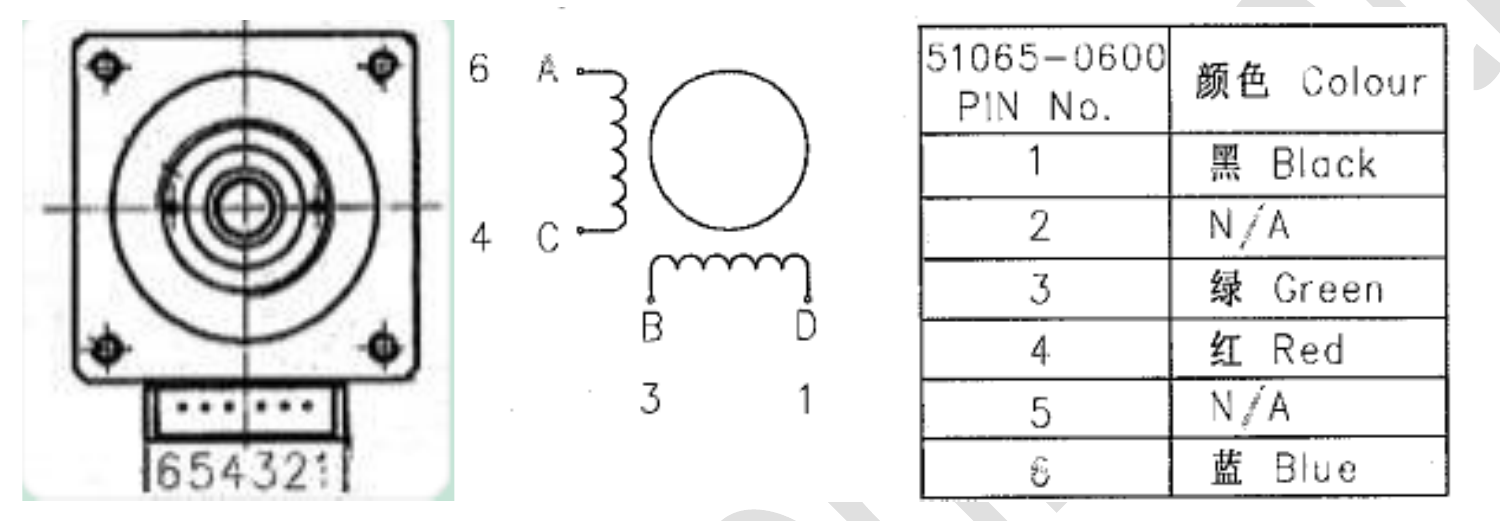
View material compatibility referencesSM motor versions have different current, resistance and wire colours. Check the motor label and matching drawing before driver setup; the 28-size housing is insufficient identification.
| Drive voltage | 24 V DC |
|---|---|
| Rated phase current | 0.67 A/phase |
| Winding resistance | 7.2 Ω ±10% |
| Winding inductance | 5.1 mH |
| Terminal / wire colour | Winding |
|---|---|
| 6 · Blue | Winding terminal A |
| 4 · Red | Winding terminal C, paired with A |
| 3 · Green | Winding terminal B |
| 1 · Black | Winding terminal D, paired with B |
Positions 2 and 5 of the six-position connector are unused. Verify pins 1, 3, 4 and 6 from the specified viewing direction; EA motor phase numbering cannot be reused.
Rated phase current is a winding parameter, not power-supply input current. Check peak/RMS definitions. After setting microstepping and ramps, recheck motion, temperature rise and dispensing.
Use the integrated drive’s specified supply, address and protocol. Initialize and home before motion commands; check busy and error responses. Convert protocol position units using stroke and microstepping; they are not μL.
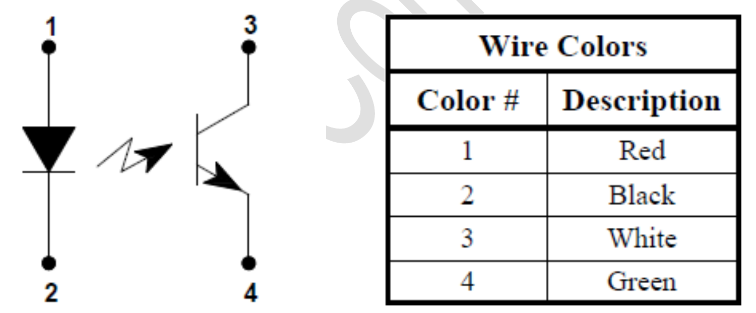
Three-, four- and five-wire sensors have different supply and output definitions. Match the supplied version. Homing detection does not provide closed-loop feedback throughout motion.
| Terminal / wire | Connection and function |
|---|---|
| Red | LED anode; connect a series current-limiting resistor before power-up |
| Black | LED cathode |
| White | Signal output; use a matching pull-up resistor |
| Green | Output logic supply return |
For a red-wire supply of 5 V, 12 V or 24 V, reference series resistors are about 200 Ω, 470 Ω or 1 kΩ respectively. Check board input levels and the white output pull-up. Measure blocked and unblocked states before setting the homing level.
Validate post-trigger stopping clearance for the mechanism, speed and stopping method. Recheck home position and usable stroke after motor, sensor or drive changes.
2 × 1/4-28 UNF flat-bottom ports; M6 optional. Match fittings, seals and tube OD as a set; even identical threads require checking port depth and sealing face.
For doses up to 20 μL, rigid tubing after the shut-off valve is recommended. Diameter, length, valve location and connections all affect delivery.
Fluid 15–40 ℃, ambient 10–40 ℃, humidity 30%–85% RH, non-condensing.Keep cleaning and extended operation within these limits too.
Confirm SM-500-PMMA capacity, head, harness and ports. Fluid temperature: 15–40 ℃; ambient: 10–40 ℃. Stop the instrument and disconnect power before changing wiring or fluid connections.
4 × M3; spacing 15 × 35 mm. Position the bracket using the mounting drawing, preferably with the outlet upward for air removal. Leave slack in tubing and wiring to avoid pulling on the head.
2 × 1/4-28 UNF flat-bottom ports; M6 optional. Check hole depth, tube outside diameter and seals together. Recommended torque for the corresponding plastic fittings is 0.25–0.30 N·m. Do not substitute PTFE tape or thread sealant for a flat-bottom seal.
Identify both windings for the selected motor, then check sensor wire colors, supply, current limiting and pull-up circuits. Verify 50 μL winding resistance separately from other SM versions.
Basic full stroke is 2000 steps. Check direction and sensor state at a controlled speed, then verify stopping clearance after triggering. Recheck command units when changing microstepping; do not use the mechanical limit as the operating endpoint.
Observe filling, bubbles and leaks in the transparent head and tubing. Coordinate aspiration, valve switching and dispensing. Collect repeated target doses and verify backlash compensation. For dosing up to 20 μL, rigid tubing downstream of the shut-off valve is recommended. Avoid prolonged dry running.
Record fluid, temperature, backpressure, target and individual collected volumes, tubing, valve timing, drive and compensation settings. Compare mean error and repeatability; retest with the same method after any change.
After maintenance, recheck home position, priming and target volume. Contact technical support for disassembly or jamming.
Nominal capacity is 500 μL with 2000 basic full-stroke steps, or 0.25 μL/step. This ratio converts motion commands. Validate the minimum reliable dose at the target volume, accounting for bubbles, backlash, valve operation and tubing elasticity.
Share the target volume, fluid compatibility, port type, control method, installation space, and service-life requirements. The Foreach engineering team can help confirm the pump configuration and wetted materials.