250 μL nominal capacity
Compare stored volume with nominal volume per step. Test the 100 and 500 μL alternatives using the same target dose, fluid and back pressure, and include refill time.

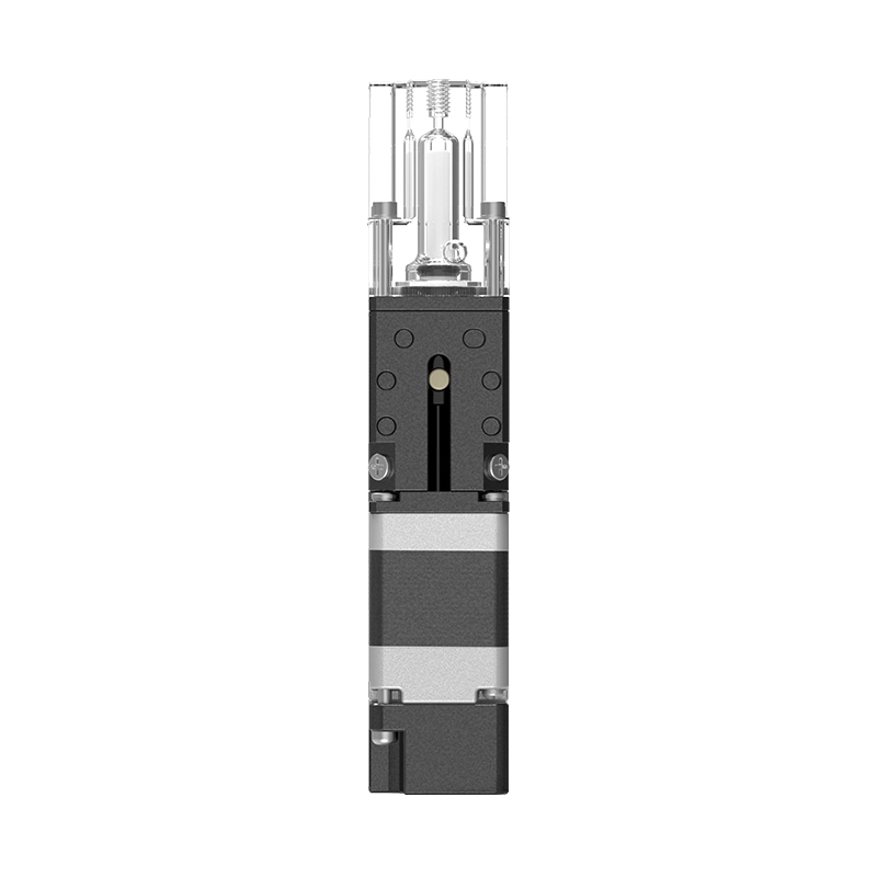
TM-250-PMMA is an OEM compact dispensing pump with a nominal capacity of 250 μL for reagent addition and metered reaction-liquid dispensing in analytical modules. Its PMMA head and ceramic piston use a stepper drive for aspiration and dispensing alongside valves and detection components.
The configuration uses 6-40 UNF ports and 2540 steps per full stroke. Valve assemblies and drive controls support staged dispensing and fluid-path switching in analytical modules. Accuracy, repeatability and service-life specifications are confirmed for the project configuration.
Mounting, tubing connections, valves and drive controls can be configured for the project. Alternative head and piston materials can be assessed against reaction-liquid chemistry, seal design and available space, with the final configuration defined by instrument requirements and the project drawing.
Application Areas:
Select capacity, pump head material and accessories, then save different configurations for your inquiry.
| Nominal capacity | 250 μL |
|---|---|
| Pump head material | PMMA (polymethyl methacrylate); Transparent |
| Piston material | Ceramic |
| Fluid port | 6-40 UNF port |
| Basic motor configuration | 1.8°; 2540 steps per full stroke |
| Nominal resolution | 0.098425 μL/step (250 μL ÷ 2540 steps) |
| Mounting | 2 × M3; spacing 15 mm, thread depth 3.5 mm |
| Accuracy / repeatability at 100% stroke | <0.5% / <0.5% |
| Repeatability at 2% stroke | <1.5% (with backlash compensation) |
| Backlash | <2.0%; validate compensation for precise dosing |
| Fluid pressure | <0.30 MPa |
| Expected service life | 3 million cycles |
| Fluid / ambient operating temperature | 15–40 ℃ / 5–40 ℃ |
| Operating humidity | 30%–85% RH, non-condensing |
| Pump weight | 96 g |
Nominal resolution is capacity divided by full-stroke steps, not the minimum reliable dose. 2% of 250 μL is 5 μL. Validate actual reagent results at this dose with the selected valves, tubing, back pressure and drive settings.
Low-range repeatability assumes backlash compensation. Match wiring, ports and mounting holes to the supplied version; do not transfer them between series.
TM-250-PMMA is designed for aspiration and metered dispensing inside instruments. The ultra-compact design suits restricted installation space. Check fitting size, small-volume performance and the external optical-sensor circuit together.
Compare stored volume with nominal volume per step. Test the 100 and 500 μL alternatives using the same target dose, fluid and back pressure, and include refill time.
The transparent head allows observation of filling and bubbles. PMMA (polymethyl methacrylate) is not resistant to alcohol or strong acids; both process and cleaning fluids must meet these material limits.
2 × M3; spacing 15 mm, thread depth 3.5 mm. Pump weight is 96 g. Allow space for tubing and cable bends in the instrument layout.
Use the 1.8° step angle with the 2540-step full stroke. Recalculate commands when changing microstepping.
TM requires a two-phase stepper driver, with the optical sensor connected to the control board for homing. Valves and controllers are specified separately for the instrument. Motor and sensor harnesses are not serial communication interfaces.
Fluid temperature 15–40 ℃, Fluid pressure <0.30 MPa. Expected service life 3 million cycles; validate with the actual fluid, drive and maintenance conditions.
Compare stored volume with nominal volume per step. Test the 100 and 500 μL alternatives using the same target dose, fluid and back pressure, and include refill time.
| Step angle | Full steps per stroke | Nominal volume per step |
|---|---|---|
| 2540 steps | 0.098425 μL/step |
254steps
25 μL ÷ 250 μL × 2540 steps = 254 steps
Nominal steps are for command conversion, not the minimum reliable dose or measured accuracy.Calculated from capacity and full-stroke steps; volume per step is rounded for display. Validate microstepping, backlash, bubbles, valves and tubing at the target volume.
Backlash is <2.0%. Determine compensation in the actual circuit; do not use 2% of full stroke as a fixed compensation command.
This model has a PMMA (polymethyl methacrylate) head and ceramic piston. The transparent head allows observation of filling and bubbles. PMMA (polymethyl methacrylate) is not resistant to alcohol or strong acids; both process and cleaning fluids must meet these material limits.
Record ingredients, concentration, temperature and contact time. PMMA (polymethyl methacrylate) cannot be used with alcohol or strong acids. For another material, confirm TM availability and mounting dimensions first.
Check ceramic piston, seals, fittings, tubing and valves. After changing head material, revalidate sealing and dispensing. EA material options are not default TM configurations.
TM has a rated phase current of 0.5 A and uses a two-phase stepper driver. Connect winding pairs, then match current settings and start/stop ramps.
| Rated phase current | 0.5 A/phase |
|---|---|
| Winding resistance | 5.1 Ω ±10% |
| Winding inductance | 1.5 mH ±20% |
| Terminal / wire colour | Winding |
|---|---|
| Red | A+ |
| Red/white | A− |
| Green | B+ |
| Green/white | B− |
Connect the two wires of each phase to the matching driver outputs. Observe rotation from the mounting face. Match TM current, wire colors and stroke steps independently; EA and SM pin numbering does not apply.
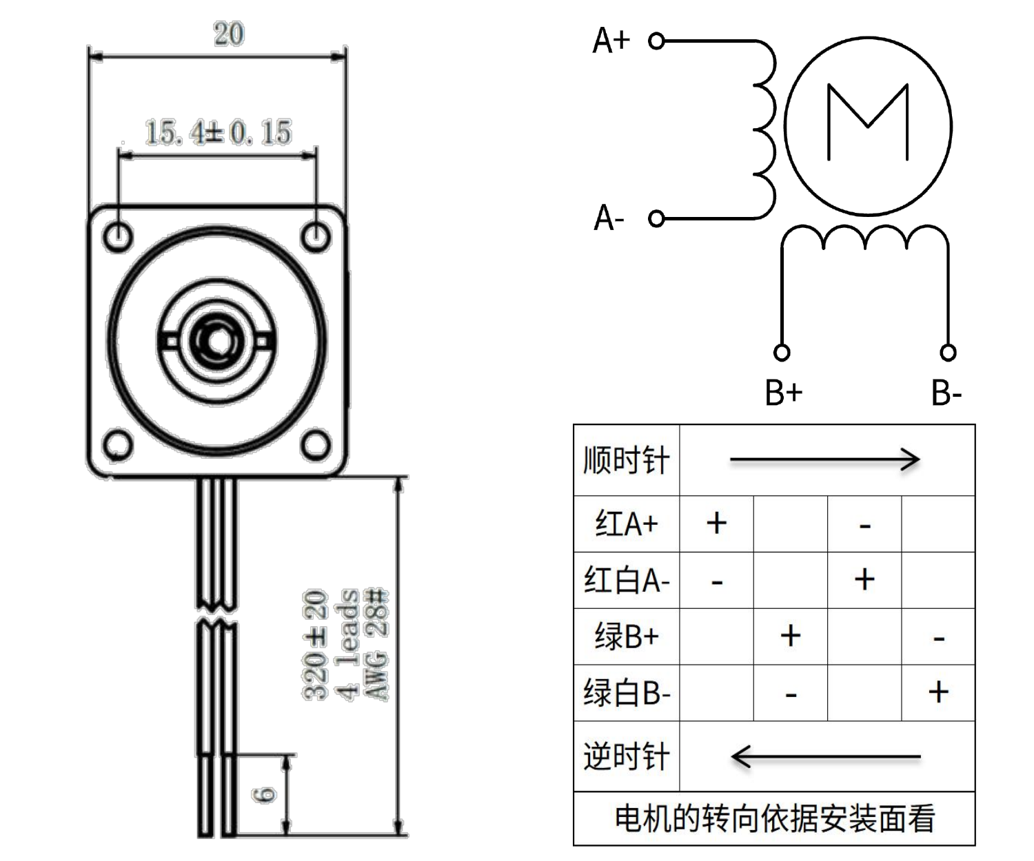
Rated phase current is a winding parameter, not power-supply input current. Check peak/RMS definitions. After setting microstepping and ramps, recheck motion, temperature rise and dispensing.
Stepper motor acceleration and decelerationWire TM emitter and detector sides separately, including external current-limiting and pull-up resistors. Verify both optical states before setting homing direction and stop logic.
| Terminal / wire | Connection and function |
|---|---|
| A | LED anode; series current-limiting resistor Rf |
| K | LED cathode; ground |
| E | Phototransistor emitter; ground |
| C | Phototransistor collector; output with pull-up RL |
At Vcc = 5 V, recommended Rf is 150–200 Ω and RL is 10 kΩ. Neither resistor is fitted to the adapter board; provide both externally. Recalculate for other supply voltages. Do not use maximum rated current as the operating setting.
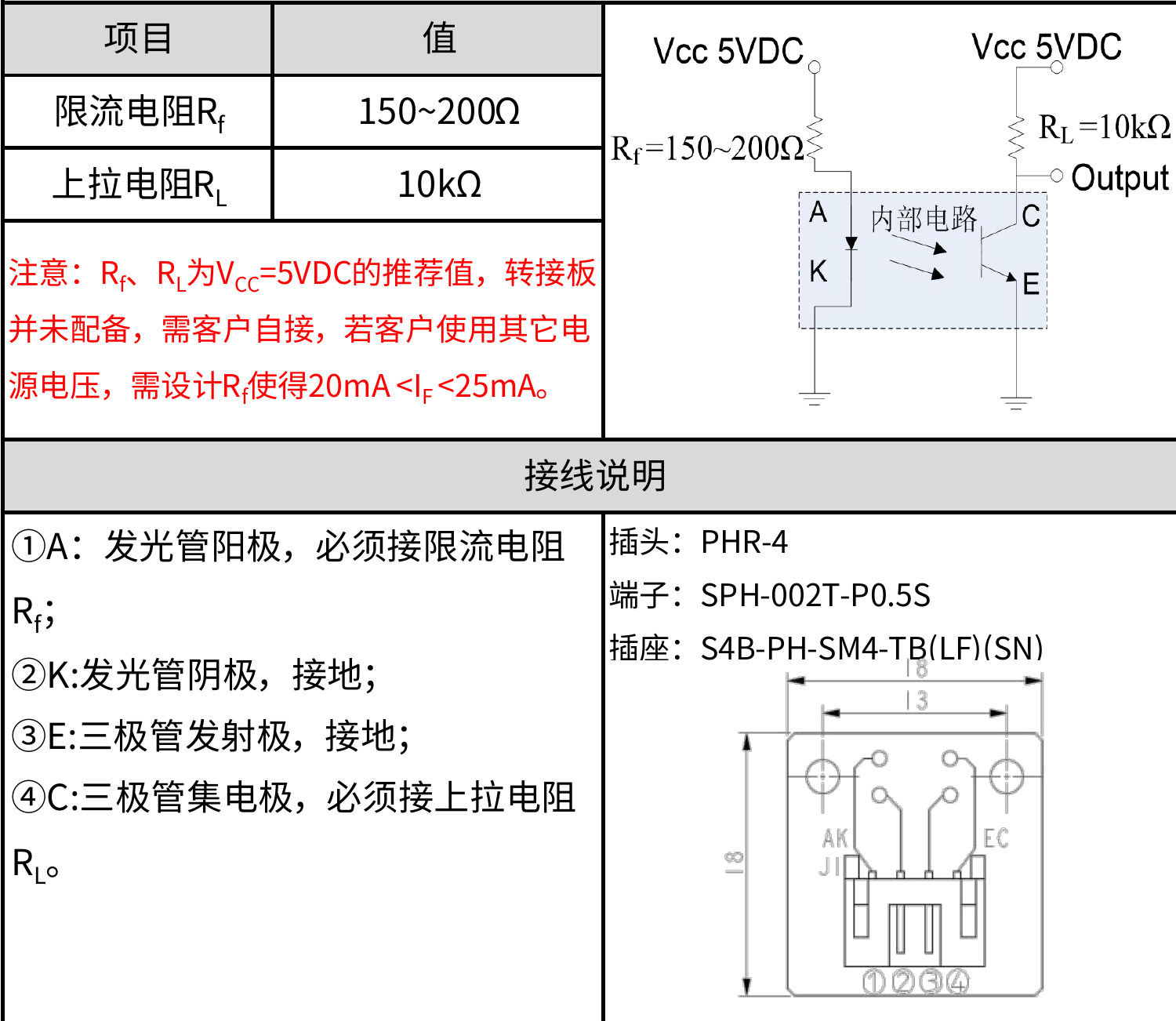
Validate post-trigger stopping clearance for the mechanism, speed and stopping method. Recheck home position and usable stroke after motor, sensor or drive changes.
6-40 UNF port. Check fine-thread fittings, seals and insertion depth. Do not use larger fittings from other series.
Minimize unnecessary residual volume within installation constraints. Check bubbles, valve switching and outlet drips. Retest at the same target volume after tube diameter or length changes.
Fluid 15–40 ℃, ambient 5–40 ℃, humidity 30%–85% RH, non-condensing.Keep cleaning and extended operation within these limits too.
Confirm TM-250-PMMA capacity, head, harness and ports. Fluid temperature: 15–40 ℃; ambient: 5–40 ℃. Stop the instrument and disconnect power before changing wiring or fluid connections.
2 × M3; spacing 15 mm, thread depth 3.5 mm. Check screw engagement against bracket thickness to prevent intrusion into the mechanism. Verify the mounting face and motor outline separately.
6-40 UNF port. Check fitting thread, insertion depth and seal type. Never force 1/4-28 UNF or M6 fittings into these ports. Use the tightening method specified for the selected fitting.
Identify phases by red/red-white and green/green-white pairs. Connect the sensor by A/K/E/C. Before power-up, verify external Rf and RL against the 5 V reference circuit or another validated supply design.
Basic full stroke is 2540 steps. Check direction and sensor state at a controlled speed, then verify stopping clearance after triggering. Recheck command units when changing microstepping; do not use the mechanical limit as the operating endpoint.
Observe filling, bubbles and leaks in the transparent head and tubing. Coordinate aspiration, valve switching and dispensing. Collect repeated target doses and verify backlash compensation. For very small doses, check residual tubing volume, bubbles and valve-switching error together. Avoid prolonged dry running.
Record fluid, temperature, backpressure, target and individual collected volumes, tubing, valve timing, drive and compensation settings. Compare mean error and repeatability; retest with the same method after any change.
After maintenance, recheck home position, priming and target volume. Contact technical support for disassembly or jamming.
Nominal capacity is 250 μL with 2540 basic full-stroke steps, or 0.098425 μL/step. This ratio converts motion commands. Validate the minimum reliable dose at the target volume, accounting for bubbles, backlash, valve operation and tubing elasticity.
Share the target volume, fluid compatibility, port type, control method, installation space, and service-life requirements. The Foreach engineering team can help confirm the pump configuration and wetted materials.