
How to Select a Gas-Liquid Diaphragm Pump: DPGL800 Flow, Vacuum and Build-Up Time
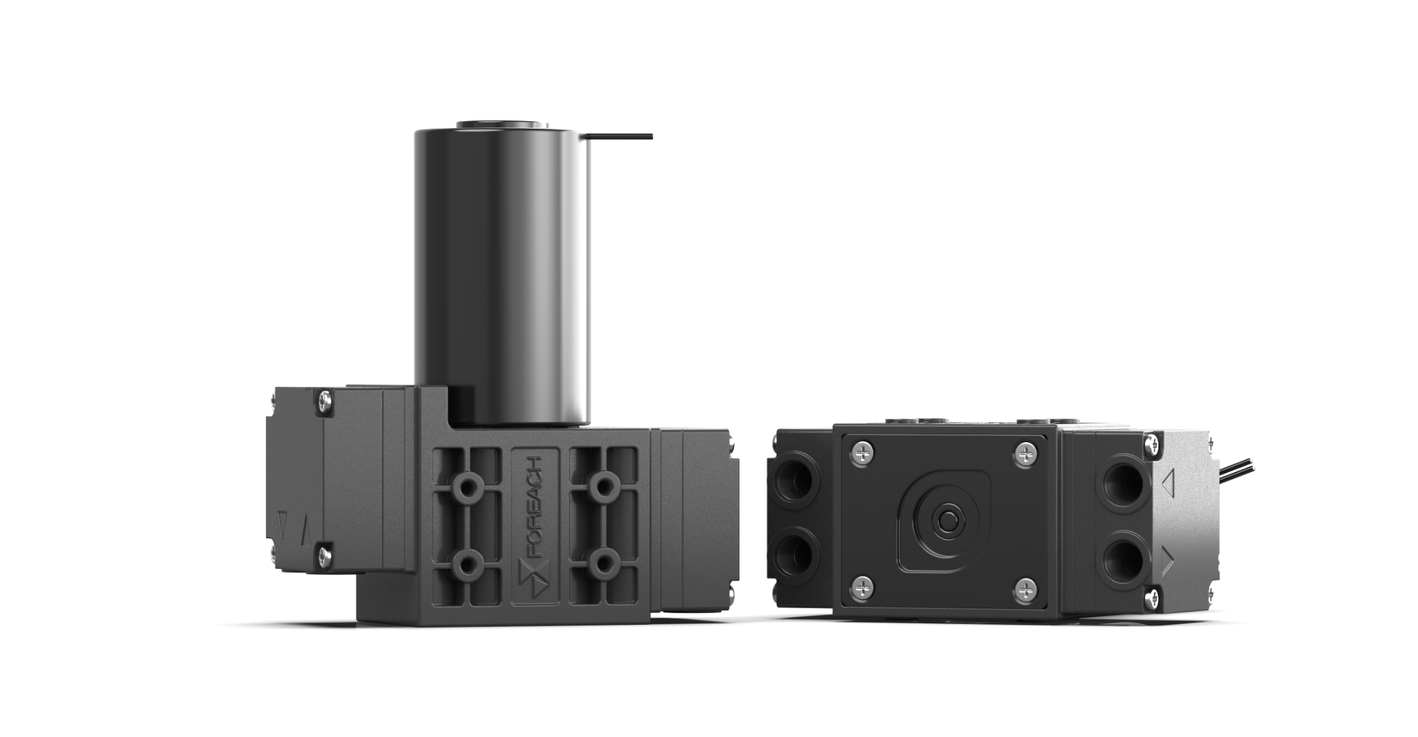
1. Why DPGL800 is not selected like an ordinary liquid pump
DPGL800 is intended for gas and gas-liquid mixtures. Typical duties include aspirating waste liquid with entrained air, evacuating tubing, creating vacuum and continuing to draw when liquid arrives intermittently.
Selection therefore requires more than one flow figure. Define the medium state, target vacuum, permitted build-up time, system volume, discharge pressure, line losses, wetted materials and installation interface. DPGL800-24BS is a 24 V brushless platform operating at DC 24 V ±10% with power consumption of ≤17 W.
2. Information to define before selection
These inputs determine whether 6 L/min and <-90 kPa match the real duty.
| Item | Information required | Why it matters |
|---|---|---|
| Medium state | Gas, gas-liquid mixture or intermittent liquid slugs; foam and particles | Determines pump type, materials and validation |
| Suction target | Target vacuum and time allowed to reach it | Ultimate vacuum and evacuation speed are different |
| System volume | Effective gas volume of chamber, tubing, filters and accessories | Volume directly changes build-up time |
| Discharge condition | Open exhaust or backpressure; required positive pressure | Backpressure changes the operating flow |
| Fluid path | Tube length and bore, valves, fittings, filters, seals and leak rate | Restriction and leakage slow evacuation |
| Medium and temperature | Composition, concentration and operating temperature within +5℃ to +40℃ | Required for compatibility review |
| Installation | Space, G1/8 female ports, port direction and wiring | Confirms mechanical integration |
3. What does 6 L/min mean?
The 6 L/min rating is the single-head, no-load gas-flow capability. It identifies the performance class, but it is neither an actual pure-liquid flow rate nor a fixed installed flow at every vacuum or backpressure.
Flow changes as inlet vacuum deepens or discharge resistance rises. Tubing, valves, fittings, filters, sealing, liquid slugs and the medium state also affect the installed result. Use the curve to locate the required pressure point, then validate the complete system.
The first is a no-load gas-flow reference; the second is maximum vacuum capability. DPGL800 is not specified to deliver 6 L/min at <-90 kPa.
4. Core DPGL800-24BS specifications
These fixed limits must remain consistent; confirm material and port-direction details from the complete model code.
| Parameter | DPGL800-24BS |
|---|---|
| Motor | Brushless DC |
| Operating voltage | DC 24 V ±10% |
| Power | ≤17 W |
| Single-head no-load flow | 6 L/min (gas capability, not actual pure-liquid flow) |
| Maximum positive pressure | 30 kPa |
| Maximum negative pressure / vacuum | <-90 kPa |
| Media | Gas and gas-liquid mixtures |
| Medium / ambient temperature | +5℃ to +40℃ |
| Ports | G1/8 female thread |
| Weight | Approx. 600 g |
| Specified life | 10000 h at rated voltage, continuous operation |
| Wetted materials | Polyphenylene sulfide (PPS) head; EPDM or PTFE diaphragm and EPDM or FFKM valve, depending on model |
5. Reading the gas flow-pressure curve
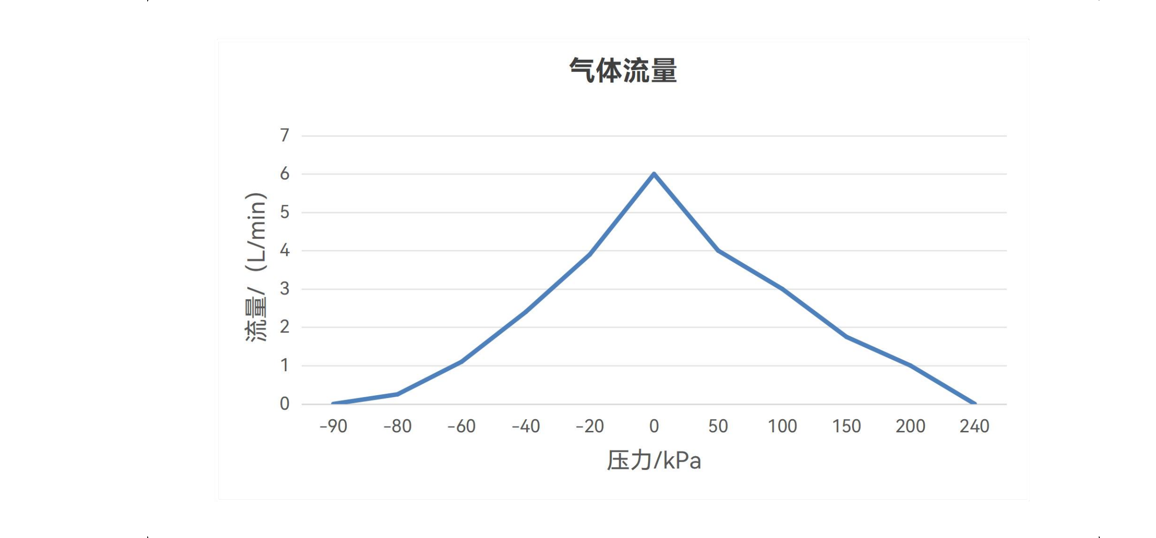
The curve connects gas flow with pressure. Flow is approximately 6 L/min near zero differential pressure, then changes as inlet vacuum or outlet pressure increases.
Start with the pressure range required by the instrument and read the available flow at that point with suitable margin. The chart illustrates the trend; the formal maximum positive-pressure limit remains 30 kPa.
6. What the 5 L vacuum build-up curve means
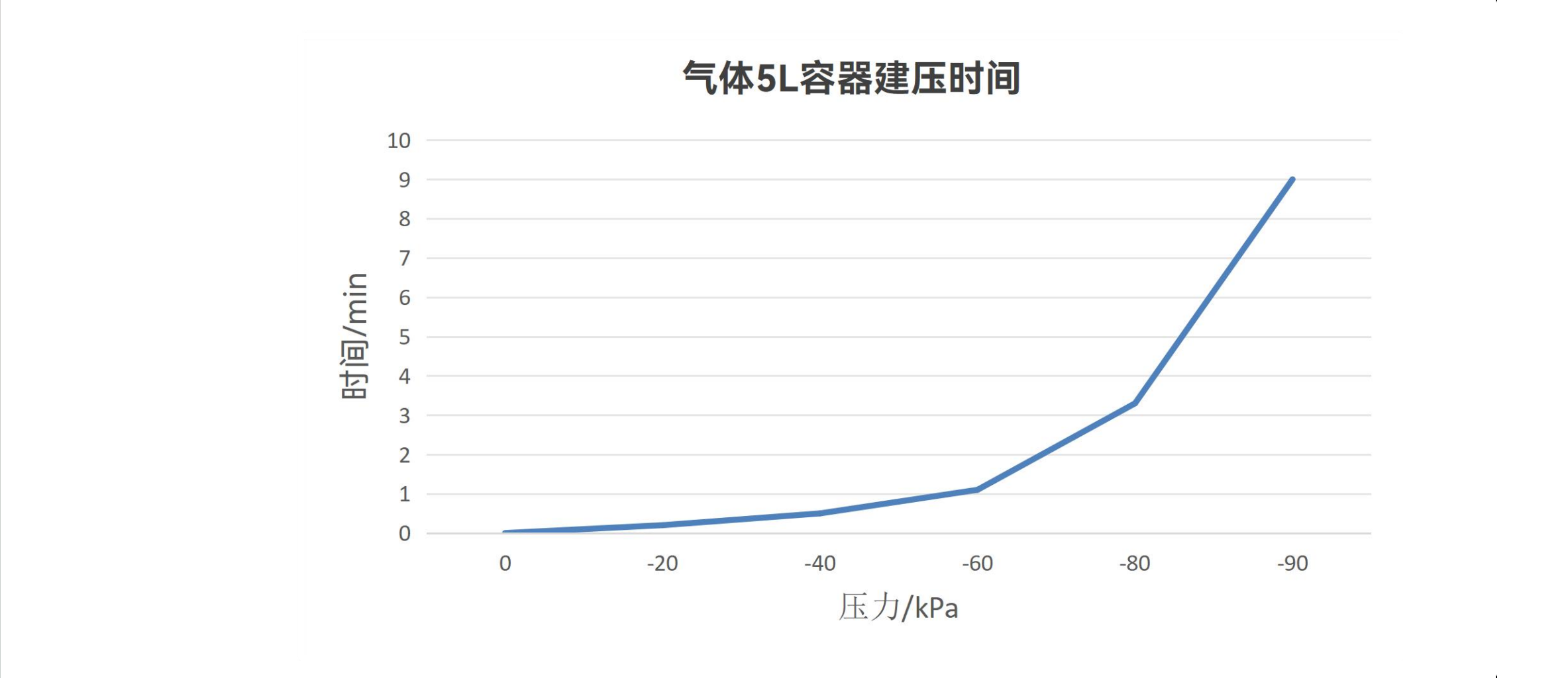
This curve records the time needed to build vacuum in a fixed 5 L test chamber and defined test circuit. The final part of evacuation normally takes longer as the pressure approaches the pump's vacuum limit, so time is not a simple linear conversion.
The 5 L value is a test condition, not a capacity, product or application limit. Real 0.5 L, 2 L or 10 L systems behave differently and are also affected by tubing volume, valves, fittings, filters, sealing and leakage.
7. Gas-liquid aspiration versus continuous pure-liquid transfer
DPGL800 fits gas handling, gas-liquid aspiration, waste extraction, line evacuation and vacuum generation. Its 6 L/min value is a gas rating and must not be used as a continuous metered pure-liquid flow.
For stable pure-liquid transfer, compare pumps using liquid flow at pressure, self-priming, pulsation and material compatibility. For a duty with substantial air or high vacuum, validate DPGL800 in the actual gas-liquid circuit.
For a 600 mL/min-class continuous liquid-transfer option, read the DPL60 liquid diaphragm pump selection guide.
8. G1/8 ports, dimensions and port direction
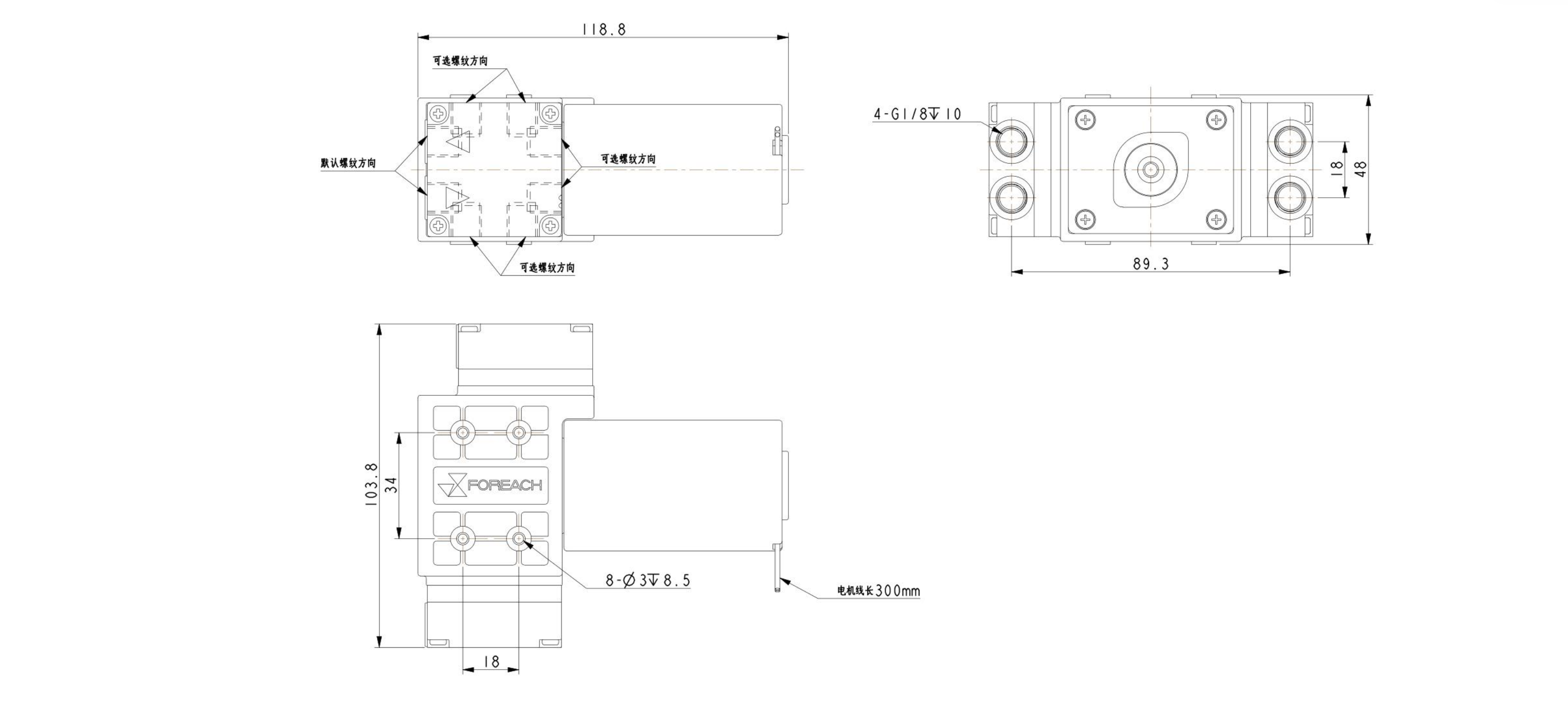
DPGL800 uses G1/8 female threads. Fitting bore, sealing method and line diameter affect restriction and leakage, so the thread designation alone is insufficient. Check the approximately 118.8 mm overall length, mounting holes, approximately 600 g weight and cable clearance before release.
The model code identifies port direction. The drawing shows available thread orientations; the delivered direction must match the confirmed full model and drawing.
| Code | Direction | Integration check |
|---|---|---|
| 3 | Right | Right-side fitting and service clearance |
| 6 | Down | Lower tube bend radius |
| 9 | Left | Left-side fitting and service clearance |
| C | Up | Upper tube and enclosure clearance |
9. DPGL800 model coding and interpretation
The complete code defines series, voltage, motor, connection, port direction, wetted materials and special customization.
Series · voltage · brushless motor · threaded connection · port direction · diaphragm/valve/head materials · customization
| Field | Code | Meaning |
|---|---|---|
| Series | DPGL800 | Gas and gas-liquid diaphragm pump |
| Voltage | 24 / 12 | DC 24 V; 12 V exists in the coding rules |
| Motor | B | Brushless DC |
| Connection | S | G1/8 female thread |
| Port direction | 3 / 6 / 9 / C | Right / down / left / up |
| Wetted materials | EP/PS / FF/PS | EPDM+EPDM+PPS / PTFE+FFKM+PPS |
| Customization | X | Identifier for a special configuration |
Example: DPGL800-24BS6-EP/PS
DPGL800 series, 24 V, brushless motor, G1/8 female thread, downward ports, EPDM diaphragm, EPDM valve and PPS head.
10. Complete DPGL800 selection sequence
- Define the medium
Record gas-liquid ratio, intermittent slugs, foam, particles and any sustained liquid phase.
- Set vacuum and cycle time
State both target vacuum and permitted build-up time, not only <-90 kPa.
- Calculate effective volume
Include the chamber, tubing, filters, valves and accessories.
- Define discharge backpressure
Use the curve to locate the real operating point.
- Review wetted materials
Select EP/PS or FF/PS using composition, concentration, temperature and contact time.
- Choose port direction
Select 3, 6, 9 or C and check G1/8 fittings, tubing and service space.
- Check power and life
Provide DC 24 V ±10% and evaluate ≤17 W and the 10000 h continuous-duty condition.
- Validate the system
Test vacuum, build-up time, flow, leakage, noise, temperature rise and gas-liquid transitions.
11. Material combinations and boundaries
Compatibility must cover the entire wetted path, including head, diaphragm, valve, fittings, seals and tubing.
| Combination | Construction | Selection note |
|---|---|---|
| EP/PS | EPDM diaphragm + EPDM valve + PPS head | Baseline combination for evaluation; validate with the real medium |
| FF/PS | PTFE diaphragm + FFKM valve + PPS head | For more demanding compatibility reviews; not universal chemical compatibility |
| Temperature | +5℃ to +40℃ | Both medium and ambient must remain within the range |
| Life | 10000 h | At rated voltage and continuous operation; load, temperature, cycling and medium affect actual life |
Conclusion
Treat the 6 L/min no-load gas flow, <-90 kPa maximum vacuum and 5 L test-chamber build-up time as separate selection inputs. Then apply the real volume, pressure loss, leak rate, medium and material requirements.
Use a liquid diaphragm pump such as DPL60 for continuous pure-liquid transfer comparisons. Use DPGL800 for duties involving air, waste aspiration, evacuation or high vacuum, subject to validation in the actual circuit.
See available configurations, dimensions and downloads on the DPGL800 gas-liquid diaphragm pump product page.
To compare other flow, pressure and medium ranges, return to diaphragm pumps.