
How to Select a 300 mL/min Liquid Diaphragm Pump: DPL30 Working Principle and Model Guide
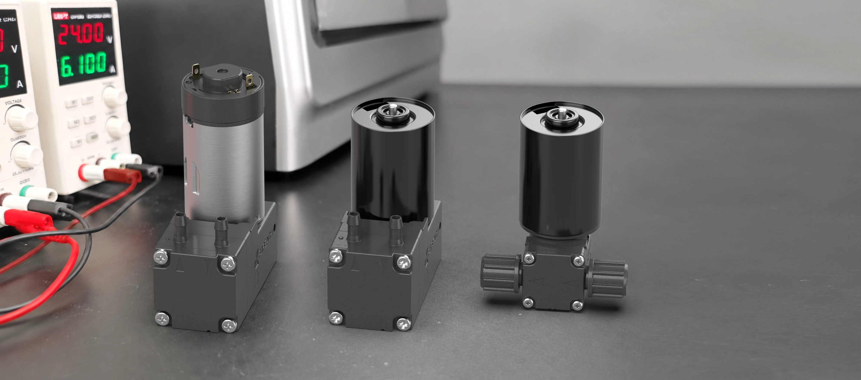
1. How does a liquid diaphragm pump draw in and discharge liquid?
A liquid diaphragm pump is a positive-displacement pump that transfers liquid through the reciprocating motion of a flexible diaphragm. Its main structure includes a pump chamber, diaphragm, inlet valve, outlet valve, and drive mechanism.
The motor drives the diaphragm back and forth through an eccentric mechanism, causing the pump-chamber volume to vary cyclically. During the suction stroke, diaphragm motion increases the chamber volume and reduces the chamber pressure below the inlet pressure; the inlet valve opens, the outlet valve closes, and liquid is drawn into the chamber. During the discharge stroke, the diaphragm reverses direction, reducing the chamber volume and raising the chamber pressure; the inlet valve closes, the outlet valve opens, and liquid is forced into the downstream line.
The diaphragm also separates the conveyed medium from the drive mechanism. The liquid mainly contacts the pump head, diaphragm, and valve plates, so different wetted-material combinations can be evaluated for different liquids.
Reciprocating operation produces a certain amount of flow and pressure pulsation. Pulsation is affected by chamber geometry, speed, diaphragm stroke, valve response, tubing elasticity, system back pressure, and damping structures. Equipment with strict flow-stability requirements should be verified in the complete fluidic circuit.
2. What must be confirmed when selecting a liquid diaphragm pump?
A label of “300 mL/min” alone is not enough to select a diaphragm pump. Reliable selection also requires confirmation of the liquid, flow test conditions, system pressure, self-priming height, wetted materials, motor type, operating time, and fluidic resistance.
| Selection item | What to confirm | Common mistake |
|---|---|---|
| Liquid medium | Liquid name, concentration, temperature, viscosity, particles, and continuous contact time | Assuming PTFE or FFKM means the pump is compatible with every chemical |
| Flow rate | Whether the stated value is no-load, rated, maximum, or operating flow at a specified pressure | Treating no-load flow as the actual flow in the instrument |
| Pressure | Resistance from downstream filters, tubing, fittings, valves, nozzles, and liquid-level difference | Looking only at maximum pressure instead of flow at the target pressure |
| Self-priming | Height difference between the liquid level and pump inlet, and whether the line is initially filled | Treating the datasheet priming height as guaranteed stable suction under all conditions |
| Wetted materials | Materials of the pump head, diaphragm, and valve plates | Checking only the diaphragm and ignoring the valves and pump head |
| Motor and lifetime | 12 V or 24 V, daily operating time, and continuous or intermittent duty | Using lifetime figures without their test conditions |
| Tubing conditions | Tubing inner diameter, length, bends, filters, and number of fittings | Ignoring the effect of line resistance on actual flow |
| Pulsation and noise | Whether the system has defined requirements for flow stability, vibration, and sound | Describing a diaphragm pump as completely pulse-free or silent |
3. Why can DPL30 not be selected by 300 mL/min alone?
The “300 mL/min” value must be interpreted together with its test conditions. It may refer to no-load flow, maximum flow, rated flow, or operating flow at a specified pressure.
The rated pressure is 100 kPa. These values are not the same operating point and do not mean that DPL30 still delivers 300 mL/min at 100 kPa.
After the pump is installed in equipment, tubing, filters, fittings, valves, nozzles, and liquid-level difference all create fluidic resistance. Actual flow changes as inlet vacuum or outlet pressure increases.
Therefore, “a pump with about 300 mL/min no-load flow” and “300 mL/min at the actual system pressure” are different requirements. For the latter, first confirm the system pressure, then determine the operating point from the flow-pressure curve and installation testing.
4. Complete DPL30 technical specifications
DPL30 is available in 12 V and 24 V versions with brushed or brushless motors. The following values are organized from the current DPL30 datasheet.
| Parameter | Brushed version | Brushless version |
|---|---|---|
| Product name | DPL30 Liquid Diaphragm Pump | |
| Base models | DPL30-24DB, DPL30-12DB | DPL30-24BB, DPL30-12BB |
| Motor type | DC brushed motor | DC brushless motor |
| Rated voltage | DC 12V ±10% or DC 24V ±10% | |
| Rated power | ≤8W | |
| No-load flow | 300 mL/min | |
| Rated pressure | 100 kPa | |
| Self-priming height | 6 mH₂O | |
| Working medium | Purified water; other liquids must be evaluated by the customer under actual operating conditions | |
| Medium temperature | +5℃ to +80℃ | |
| Tube connection | For tubing with 3.2 mm inner diameter | |
| Pump-head material | PPS | |
| Diaphragm material | EPDM or PTFE | |
| Valve material | EPDM or FFKM | |
| Weight | Approx. 160 g | Approx. 185 g |
| Lifetime | 3000 h at rated voltage, continuous operation | 10000 h at rated voltage, continuous operation |
| Noise | ≤80 dB | |
| Operating ambient temperature | +5℃ to +40℃ | |
| Operating relative humidity | 30% to 85% RH, non-condensing | |
| Storage temperature | -10℃ to +40℃ | |
| Storage relative humidity | 10% to 90% RH, non-condensing | |
5. How should the DPL30 flow-pressure curve be read?
The flow-pressure curve shows how DPL30 flow changes with inlet vacuum and outlet positive pressure. The left side of the horizontal axis represents inlet vacuum, the right side represents outlet pressure, and the vertical axis represents flow.
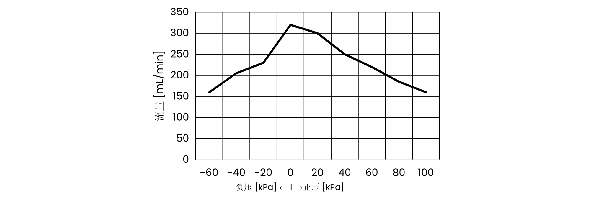
Under near no-load conditions, DPL30 flow is about 300 mL/min. Actual flow gradually decreases as outlet pressure rises, and it also falls as inlet vacuum increases and suction becomes more difficult.
6. How should DPL30 wetted materials be selected?
The principal wetted parts of DPL30 are the pump head, diaphragm, and valve plates. Compatibility must be evaluated for the complete wetted-material combination.
| Wetted part | Available material | Model-code relationship |
|---|---|---|
| Pump head | Polyphenylene sulfide (PPS) | PS |
| Diaphragm | EPDM or PTFE | EPDM in EP/PS; PTFE in FF/PS |
| Valve plates | EPDM or FFKM | EPDM in EP/PS; FFKM in FF/PS |
EP/PS material combination
EP/PS indicates an EPDM diaphragm, EPDM valve plates, and PPS pump head. It can be used as a basic evaluation configuration for purified water and some conventional liquids.
FF/PS material combination
FF/PS indicates a PTFE diaphragm, FFKM valve plates, and PPS pump head. It can be evaluated for applications with higher material-compatibility requirements.
Before selection, provide the liquid name, formulation, concentration, temperature, continuous contact time, cleaning method, and operating conditions, and evaluate the full wetted path.
7. How should brushed and brushless versions be selected?
The brushed and brushless versions use different motors, resulting in differences in lifetime, weight, overall length, and wiring.
| Comparison item | Brushed version | Brushless version |
|---|---|---|
| Motor type | DC brushed motor | DC brushless motor |
| Specified lifetime | 3000 h at rated voltage, continuous operation | 10000 h at rated voltage, continuous operation |
| Typical direction | Equipment with limited operating time and tighter cost targets | Equipment with longer operating time and higher instrument-lifetime requirements |
| Weight | Approx. 160 g | Approx. 185 g |
| Control method | Basic positive/negative power connection | PWM, direction control, or speed feedback may be available depending on configuration |
Lifetime data must not be separated from its test conditions. System back pressure, supply variation, ambient temperature, frequent start-stop cycles, installation heat dissipation, and liquid condition can all affect actual service life.
Brushed-version dimensions
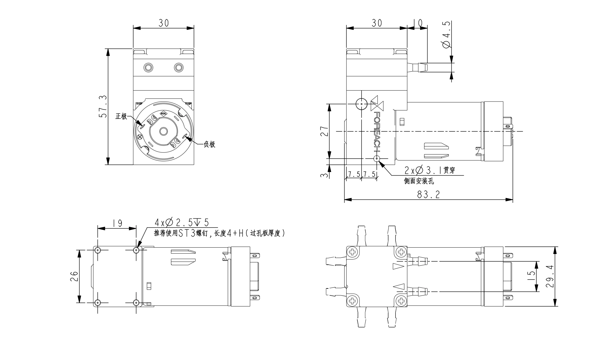
The brushed version is approximately 83.2 mm long and 57.3 mm high, with a maximum body width of about 30 mm and a pump-head body width of about 26 mm. The barb outer diameter is about φ4.5 mm for tubing with a 3.2 mm inner diameter. Use the official dimensional drawing for exact mounting holes, dimensions, and port orientation.
Brushless-version dimensions
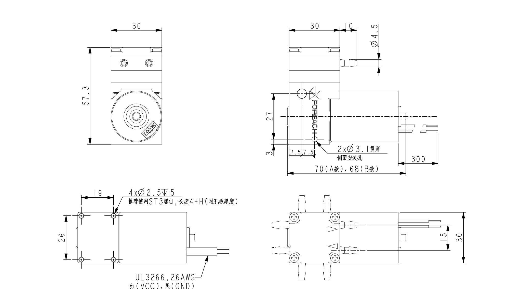
The brushless version can use two equivalent motor materials, A and B, with the same electrical parameters and output performance. Their main difference is the mounting envelope. The body length is approximately 70 mm or 68 mm, the overall height is about 57.3 mm, and the maximum body width is about 30 mm.
8. DPL30 model-code explanation and available configurations
A complete DPL30 model code consists of the product series, operating voltage, motor type, wire configuration, connection type, port orientation, diaphragm/valve and pump-head materials, and a special customization code.
Product series · Operating voltage · Motor type · Wiring · Connection · Port orientation · Wetted materials · Special customization
| Field | Code | Meaning |
|---|---|---|
| Product series | DPL30 | DPL30 liquid diaphragm pump series |
| Operating voltage | 24 / 12 | DC 24V / DC 12V |
| Motor type | D / B / C / BP | D: DC brushed motor; B: DC brushless motor; C: coreless motor; BP: DC brushless motor with external PWM |
| Wiring | 2 / 3 / 5 | 2-wire, 3-wire, or 5-wire; the default 2-wire code may be omitted |
| Connection | B / S | B: barb port; S: threaded port |
| Port orientation | 3 / 6 / 9 / C | 3: right; 6: down; 9: left; C: up and may be omitted when default |
| Diaphragm/valve and pump-head materials | EP/PS / FF/PS | EP/PS: EPDM diaphragm and valves with PPS pump head; FF/PS: PTFE diaphragm, FFKM valves, and PPS pump head |
| Special customization | X | Custom code; the final project confirmation document prevails |
Model example: DPL30-24DB-EP/PS
This model can be expanded as DPL30-24-D-2-B-C-EP/PS: DPL30 series, DC 24V, DC brushed motor, 2-wire, barb port, upward port orientation, EPDM diaphragm and valve plates, and PPS pump head.
9. Complete DPL30 selection procedure
- Confirm the target flow
Distinguish between approximately 300 mL/min no-load flow and a required operating flow at the actual system pressure.
- Confirm system pressure
Estimate resistance from filters, tubing, fittings, valves, nozzles, and liquid-level difference, then use the flow-pressure curve.
- Confirm the liquid
Provide the liquid name, formulation, concentration, temperature, viscosity, particles, and continuous contact time.
- Select operating voltage
Choose DC 12V or DC 24V according to the instrument power supply.
- Select motor type
Evaluate the brushed version for limited operating time and tighter cost targets; prioritize the brushless version for longer operating time or higher lifetime requirements.
- Confirm wiring and control
Confirm 2-wire, 3-wire, or 5-wire requirements and whether PWM, DIR, and FG functions are needed.
- Confirm fluidic connection
Select a barb or threaded port according to the tubing and fluidic structure.
- Confirm port orientation
Choose up, right, down, or left according to installation space, tubing routing, bend radius, and maintenance access.
- Confirm wetted materials
Select EP/PS or FF/PS according to compatibility and evaluate the complete wetted path.
- Complete installation verification
Confirm installation space from the dimensional drawing and test flow, pressure, noise, lifetime, and operating stability in the actual fluidic circuit.
10. Application directions and usage boundaries
DPL30 can be evaluated for liquid transfer inside IVD instruments, laboratory analytical equipment, and medical equipment, including purified-water transfer, wash lines, rinse lines, and waste-liquid transfer.
| Item | Explanation |
|---|---|
| Suitable for equipment selection evaluation | Suitability for a specific instrument must be verified against the liquid, flow, pressure, operating time, and complete equipment requirements. |
| Not medical-device certification | Selection for use inside medical equipment does not mean the pump has obtained certification for a complete medical device. |
| Other liquids require evaluation | The stated working medium is purified water. Other liquids require compatibility evaluation and sample testing. |
| Do not claim long-term dry running | Current specifications do not provide an explicit guarantee for long-term dry running. Applications requiring dry running need dedicated confirmation. |
| Lifetime figures require test conditions | 3000 h and 10000 h are based on rated voltage and continuous operation. Actual lifetime is also affected by load, temperature, and start-stop frequency. |
| Final confirmation requires system testing | Curves, dimensions, and material data support selection, but final confirmation must be completed in the actual fluidic circuit and instrument. |
Conclusion
DPL30 should not be selected from the “300 mL/min” value alone. The correct sequence is to confirm the target operating flow and system pressure first, then determine the configuration from the liquid, wetted materials, power supply, motor lifetime, connection type, installation orientation, and available space.
Before selection, prepare the target operating flow, normal operating pressure, liquid name and concentration, medium temperature, daily operating time, supply voltage, tubing inner diameter and length, filter and valve configuration, installation space, and port orientation so that the appropriate DPL30 configuration can be confirmed.
Frequently Asked Questions
What does the DPL30's 300 mL/min flow rate represent?
The 300 mL/min value is the no-load flow rate stated in the current DPL30 datasheet under the specified test conditions. It does not mean that the pump will deliver 300 mL/min under every back-pressure, suction-lift, tubing, or fluid condition. Actual flow should be determined from the fluidic resistance, flow-pressure curve, and operating point.
Can the DPL30 still deliver 300 mL/min at 100 kPa?
No. The 300 mL/min value is the no-load flow rate, while 100 kPa is the rated pressure. They are separate performance parameters and do not mean that the DPL30 maintains 300 mL/min at 100 kPa. Flow under pressure should be confirmed from the flow-pressure curve and the actual fluidic circuit.
What is the self-priming height of the DPL30?
Under the specified test conditions, the DPL30 has a self-priming height of 6 mH₂O. Actual self-priming performance may vary depending on fluid properties, tubing diameter and length, inlet resistance, liquid level difference, system sealing, and installation conditions. The final performance should be verified under the actual fluidic system conditions.
Is the DPL30 suitable as a waste-liquid pump in medical or IVD equipment?
The DPL30 can be considered as one candidate for waste-liquid discharge in IVD instruments, analytical equipment, and laboratory automation systems. Final suitability should be confirmed from the waste-fluid properties, operating flow, system back pressure, self-priming requirement, wetted materials, operating time, and installation space, followed by testing in the actual fluidic circuit.
How should I choose between brushed and brushless DPL30 versions?
For equipment with limited operating time and greater cost sensitivity, the brushed version can be evaluated first. For longer operating time and higher equipment-lifetime requirements, the brushless version can be prioritized. Current datasheet values are 3000 h for the brushed version and 10000 h for the brushless version, both at rated voltage under continuous operation. These are reference values under specified test conditions, not absolute guarantees for every application.
What liquids can the DPL30 transfer?
The standard working medium specified in the current datasheet is purified water. Other liquids must be evaluated against the complete wetted-material combination, including the PPS pump head, EPDM or PTFE diaphragm, and EPDM or FFKM valve plates. The liquid name, concentration, temperature, contact time, and cleaning method must also be confirmed; pump compatibility cannot be determined from the PTFE or FFKM material name alone.
Where can I view the DPL30 datasheet?
Select the applicable DPL30 product under Related Products below this article and open its product detail page to view the currently associated datasheet. Use the page for the actual motor type and model so that documents for different configurations are not mixed.
How can I request a CAD / 3D drawing for the DPL30?
Select the applicable DPL30 model under Related Products below this article, open its product detail page, and submit a CAD / 3D drawing request there. Installation dimensions may vary by motor type and configuration, so request the drawing for the final selected model.